background image

16

1-800-892-3986      

IS072S1-I2

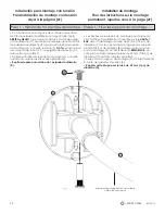
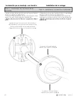
• Secure the shower rod to the walls by twisting the end of the

 7/8 in.

 diameter tube assembly (C) in the  

   direction of the 

ARROW STICKER, UNTIL SNUG.


NOTE: 

Make sure rod is level.  

• Once the rod assembly is level and secure, twist the 

7/8 in.

 diameter tube assembly (C) 

UNTIL TIGHT

.  

• 

NOTE:

 Twist the tube

 TOWARDS YOU TO LOOSEN

 the rod assembly.

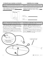
Step 6 - Installing the Rod Assembly in its final location.

Tension Mount Installation

to 

extend 

the rod

Twist the tube in the direction  

of the 

ARROW STICKER

C

to 

shorten 

the rod

Twist the tube in the  

OPPOSITE DIRECTION


of the 

ARROW STICKER

C

Содержание 72S2ALBNL

Страница 1: ...e feugait nulla facilisi et cons ectetuer adipiscing elit sed diam nonummy nibh euismod tincidunt ut laoreet dolore magna aliquam erat volutpat Ut wisi enim ad minim veniam quis nostrud exerci tation...

Страница 2: ...claim relating to this product the manufacturer will at its election and sole discretion provide a replacement product or a substantially similar product This replacement is the sole and exclusive re...

Страница 3: ...e that the tube assembly C is at the shortest position by twisting the end of the tube in the OPPOSITE DIRECTION of the arrow sticker A 1 in Mounting Bracket 1 B 7 8 in Mounting Bracket 1 C 7 8 in Dia...

Страница 4: ...3986 IS072S1 I2 List of Hardware Plastic Ring Drywall Anchor Mounting Bracket Screw Rod Set Screw Large Hex Wrench Small Hex Wrench x 1 x 2 x 1 x 2 x 1 x 4 Threaded Insert x 2 Mounting Screw x 4 1 3...

Страница 5: ...B using the mounting bracket screw 2 and threaded insert 3 NOTE The flat side of the 7 8 in diameter tube assembly C should be facing DOWN Tighten the mounting bracket screw 2 and threaded insert 3 u...

Страница 6: ...onto the tubes C NOTE Do not attach the end cap to the mounting bracket Repeat this step for the 1 in diameter tubes D NOTE Do not attach the end cap to the mounting bracket make sure end cap dimples...

Страница 7: ...H FLAT SURFACE Insert plastic ring 1 into the end of the 1 in diameter tube D fig 1 Now insert the end of the 7 8 in diameter tube assemblies C into the end of the 1 in diameter tubes D fig 2 Permanen...

Страница 8: ...in the direction of the arrow sticker by 2 turns making the assembly longer fig 1 Now extend the rod assembly to the measurement from step 4 and lock the length of the assembly with the rod set screws...

Страница 9: ...isting the end of the 7 8 in diameter tube assembly C in the direction of the ARROW STICKER UNTIL SNUG NOTE Make sure rod is level Once the rod assembly is level and secure twist the 7 8 in diameter t...

Страница 10: ...tap drywall anchors 7 into wall NOTE Do not use a wall anchor if mounting screw will be going into a stud NOTE Use a 1 4 in 6mm drill bit for drywall anchor installation Use a 1 8 in 3mm drill bit fo...

Страница 11: ...vel Once the rod assembly is secure twist the tubes until tight Complete mounting by tightening mounting screws 8 into the wall anchors 7 or studs Align the dimples on the end caps E with the notches...

Страница 12: ...ng UP and DOWN fasten the 7 8 in diameter tube assembly C to the mounting bracket for the 7 8 in diameter tube B using the mounting bracket screw 2 and threaded insert 3 NOTE The flat side of the 7 8...

Страница 13: ...nap the end cap E to the mounting bracket for the 7 8 in diameter tube B Repeat this step for the 1 in diameter tubes D Step 2 Installing the End Caps Tension Mount Installation E B make sure end cap...

Страница 14: ...T SURFACE Insert plastic ring 1 into the end of the 1 in diameter tube D fig 1 Now insert the end of the 7 8 in diameter tube assemblies C into the end of the 1 in diameter tubes D fig 2 Tension Mount...

Страница 15: ...ube in the direction of the arrow sticker by 2 turns making the assembly longer fig 1 Now extend the rod assembly to the measurement from step 4 and lock the length of the assembly with the rod set sc...

Страница 16: ...el Once the rod assembly is level and secure twist the 7 8 in diameter tube assembly C UNTIL TIGHT NOTE Twist the tube TOWARDS YOU TO LOOSEN the rod assembly Step 6 Installing the Rod Assembly in its...

Страница 17: ...d diam nonummy nibh euismod tincidunt ut laoreet dolore magna aliquam erat volutpat Ut wisi enim ad minim veniam quis nostrud exerci tation ullamcorper suscipit lobortis nisl ut aliquip ex ea commodo...

Страница 18: ...e compra y fotograf as del producto defectuoso Le fabricant garantit l acheteur initial que les trin gles gagne place et accessoires de bain NeverRust en aluminium seront exempts de rouille rouge pend...

Страница 19: ...ssemblage de tube C se trouve dans la position la plus courte en faisant tourner l extr mit du tube dans le SENS OPPOS de l tiquette fl che A Soporte de montaje de 1 pulgada Plaque de montage de 25 mm...

Страница 20: ...plaque de montage Tornillo de presi n del cortinero Vis de pression pour tringle Llave Allen hexagonal grande Grande cl hexagonale Llave Allen hexagonal peque a Petite cl hexagonale x 1 x 2 x 1 x 2 x...

Страница 21: ...our le tube de 22 mm 7 8 po de diam tre C orient es vers le HAUT et BAS fixer l assemblage de tube de 22 mm 7 8 po de diam tre C sur le support de montage pour le tube de 22 mm 7 8 po de diam tre B l...

Страница 22: ...REMARQUE Ne pas fixer le couvercle d extr mit sur le support de montage R p ter cette tape pour les tubes de 25 mm 1 po de diam tre D REMARQUE Ne pas fixer le couvercle d extr mit sur le support de mo...

Страница 23: ...extremo del tubo de 1 pulgada de di metro D ver la figura 2 REMARQUE MONTER SUR UNE SURFACE LISSE ET PLANE Ins rer la bague en plastique 1 dans l extr mit du tube de 25 mm 1 po de diam tre D fig 1 Ma...

Страница 24: ...4 hasta que queden al ras con la barra ver la figura 2 REMARQUE MONTER SUR UNE SURFACE LISSE ET PLANE Sur l assemblage de tube de 22 mm 7 8 po de diam tre C faire tourner le tube dans le sens de l ti...

Страница 25: ...de ajustado NOTA gire el tubo HACIA USTED PARA AFLOJAR el conjunto de la barra Fixer la tige de douche aux murs en faisant tourner l extr mit de l assemblage de tube 22 mm 7 8 po de diam tre C dans le...

Страница 26: ...e muraux si la vis de montage sera enfonc e dans un boulon NOTA use una broca de 1 4 de pulgada 6 mm para la instalaci n del anclaje en tablaroca Use una broca de 1 8 de pulgada 3 mm para la instalaci...

Страница 27: ...de tube de 22 mm 7 8 po C en l loignant de soi jusqu ce qu elle soit serr e REMARQUE S assurer que la tige est de niveau Une fois l assemblage de tige bien fix faire tourner les tubes jusqu ce qu ils...

Страница 28: ...o de tubo de de pulgada de di metro C debe estar cara ABAJO Apriete el tornillo del soporte de montaje 2 y el inserto roscado 3 usando las llaves Allen grandes 5 Repita este paso para el tubo de 1 pul...

Страница 29: ...montage pour le tube de 22 mm 7 8 po de diam tre B R p ter cette tape pour les tubes de 25 mm 1 po de diam tre D Paso 2 Instalaci n de las tapas de los extremos Paso 2 Installer les couvercles d extr...

Страница 30: ...extremo del tubo de 1 pulgada de di metro D ver la figura 2 REMARQUE MONTER SUR UNE SURFACE LISSE ET PLANE Ins rer la bague en plastique 1 dans l extr mit du tube de 25 mm 1 po de diam tre D fig 1 Mai...

Страница 31: ...OTA apriete el tornillo de fija ci n de la barra 4 hasta que queden al ras con la barra ver la figura 2 REMARQUE MONTER SUR UNE SURFACE LISSE ET PLANE Sur l assemblage de tube de 22 mm 7 8 po de diam...

Страница 32: ...U CE QU ELLE SOIT SERR E REMARQUE S assurer que la tige est de niveau Une fois l assemblage de tige de niveau et bien fix faire tourner l assemblage de tube de 22 mm 7 8 po de diam tre C JUSQU CE QU I...

Отзывы: