background image

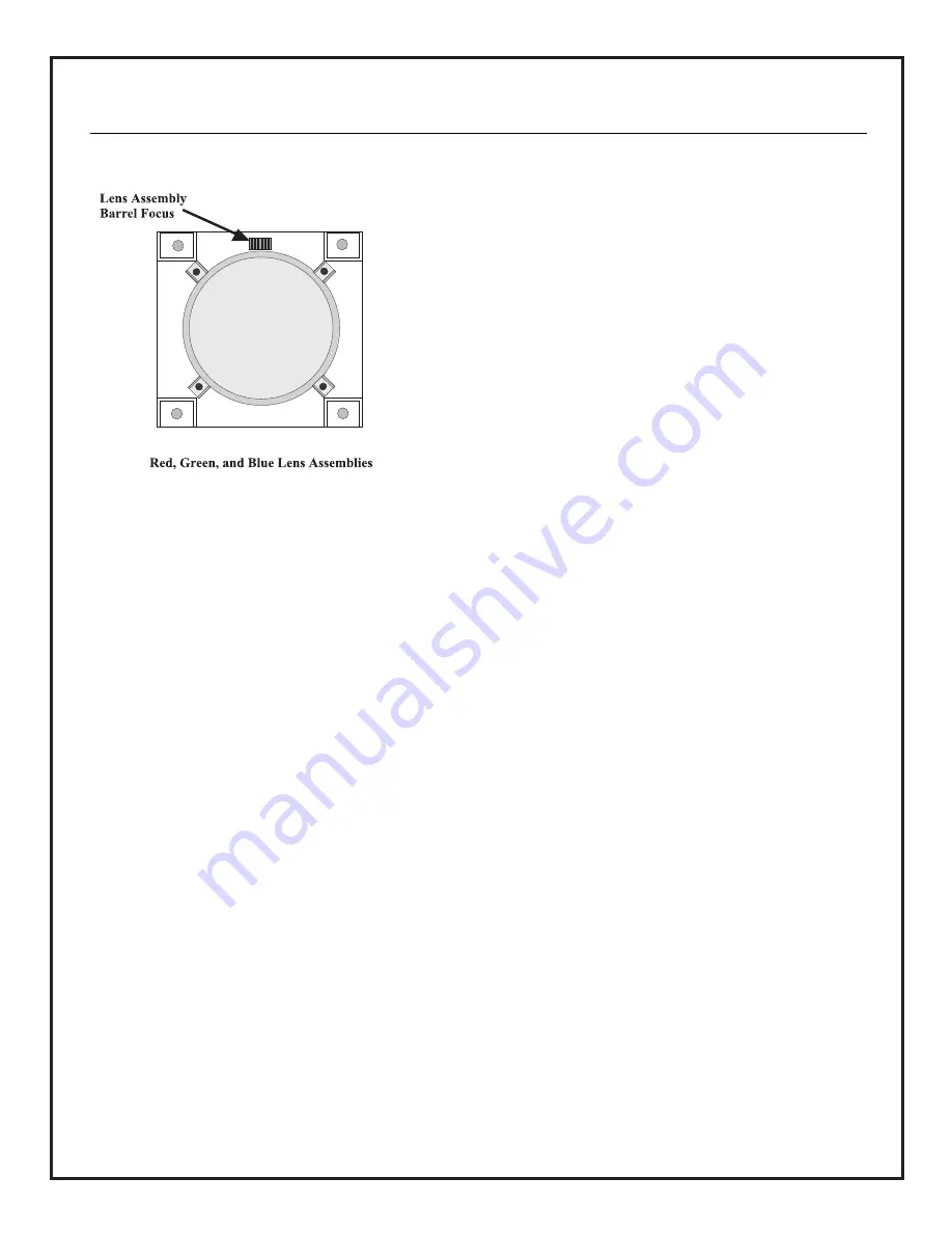
focus” spring, the following procedure must be completed. This
procedure must be completed as part of the system mechanical 
focus procedure. See the figure above.
a. Turn on the projector, project a cross-hatch pattern on the 

screen. Cover up both the Blue and Red lenses. Work only on 
the Green lens.

b. Tighten all 4 lens mounting screws.
c. Loosen all 4 lens mounting screws 3 full turns.
d. Adjust the mechanical and electrical focus to get the best 

image possible in the center of the picture.

e. Loosen the lens focus adjustment knob. Fully extend the lens 

barrel. Adjust mechanical focus while observing the center 
horizontal line. Adjust until one side (left or right) comes 
sharply into focus. Adjust the two screws opposite the side 
that is in focus (i.e., if the left side of the center horizontal 
line is in focus, adjust the two screws on the right side of the 
lens). Turn each screw 1/4 - 1/2 turn at-a-time in the same 
direction (in or out) while observing the focus of the center 
horizontal line. If the sharp focus begins to move towards the 
center of the image, you are going in the wrong direction (in or
out). Adjust in the correct direction until the entire line 
achieves a uniform soft focus from left to right. You should 
then be able to adjust the barrel focus to get the center 
horizontal line sharp all the way across. If not, you can fine 
adjust with this same procedure.

f. Loosen the lens focus adjustment knob. Fully extend the lens 

barrel. Adjust mechanical focus while observing the center 
vertical line. Adjust until one side (top or bottom) comes 
sharply into focus. Adjust the two screws opposite the side 
that is in focus (i.e., if the bottom of the center vertical 
line is in focus, adjust the two screws on the top of the 
lens). Turn each screw 1/4 - 1/2 turn at a time in the same 
direction (in or out) while observing the focus of the center 
vertical line. If the sharp focus begins to move towards the 
center of the image, you are going in the wrong direction (in or
out). Adjust in the correct direction until the entire line 
achieves a uniform soft focus from top to bottom. You should 
then be able to adjust the barrel focus to get the entire image 

sharp all the way across (top to bottom and left to right). If 
not, you can fine adjust with this same procedure.

Note:

Throughout this procedure pay no attention to the 

corners of the image.
g. Adjust the focus mechanically and electrically to get the 

best overall image.

h. Cover the Green lens and uncover the Red lens.
i.  Repeat step “b” - “g” for Red.

j. Cover the Red lens and uncover the Blue lens.
k. Repeat steps “b” - “g” for Blue.
l. Re-install PRO895X top cover. 
m. Turn off the sync forced mode 9 and return to normal video 

viewing or sync forced mode 11.

4. Rough Geometry/Convergence Setup of Green

When aligning Green, some controls are enabled in Geometry only.
This is why the alignment starts by using Green in the geometry
mode of setup. 

a. Using the setup remote control, press “SETUP” and “RED”. 

This will put the system into the “GEOMETRY MODE”. 

b. Using the setup remote control press “RED MUTE” and 

“BLUE MUTE”. You should see only the Green video.

c. Roughly set up the shape of the Green display using the 

appropriate Skew, Bow, Key, etc. controls. Adjust size, or 
phase using the customer’s video signal. Refer to pages 25, 
26, and 27 for the convergence remote control and 
procedure notes.

5. Rough Geometry/Convergence of Red and Blue

a. Using the remote control, return to the SETUP Mode and 

select the internal cross-hatch pattern. 

b. Press “RED” and mute the Blue video. 
c. Using the “Point Angle” adjustment screws, align the Red 

center point horizontally with the Green center point. 

d. Using DC vertical center, align the horizontal center line of 

the Red pattern to the horizontal center line of the Green 
pattern. 

e. Adjust Red “Size” and “Lin T/B - L/R “ to roughly match 

the Green pattern size. Refer to pages 25, 26, and 27.

f. Roughly set up the shape of the Red display using the 

appropriate Skew, Bow, Key, etc. controls. Refer to 
pages 25, 26, and 27. 

g. Press “BLUE” and mute the Red video. 

h. Using the “Point Angle” adjustment screws, align the Red 

center point horizontally with the Green center point. 

i. Using DC vertical center, align the horizontal center line of 

the Blue pattern to the horizontal center line of the Green 
pattern. 

j. Adjust Blue “Size” and “Lin T/B - L/R “ to roughly match 

the Green pattern size. Refer to pages 25, 26, and 27.

k. Roughly set up the shape of the blue display using the 

appropriate Skew, Bow, Key, etc. controls. Refer to pages 25, 
26, and 27.  

l. Press “QUIT” and “ADJ TOGGLE” to store the adjustments.

Continued on next page

P A G E   2 3

206-3634

SYSTEM ALIGNMENT

Содержание PRO895X

Страница 1: ...HD Projection Display Installation and Setup Guide for System Installer Model PRO895X ...

Страница 2: ...ermined by turning the equipment off and on the user is encouraged to try to correct the interference by one or more of the following measures Reorient or relocate the receiving antenna Increase the separation between the equipment and receiver Connect the equipment into an outlet on a circuit different from that to which the receiver is connected Consult the dealer or an experienced radio TV tech...

Страница 3: ...vergence of Red and Blue onto Green 27 Notes 28 PLACEMENT CONSIDERATIONS Room Light Ideally the PRO895X should be placed in a low light envi ronment Picture quality and the ability to see the project ed images are adversely affected by bright light conditions Placement Your PRO895X is shipped from the factory to provide an image with an 80 width as a ceiling mounted front projec tor To ensure prop...

Страница 4: ...t 120 volt 60 Hertz AC or 230 volt 50 60 Hertz AC Do not attempt to operate it on DC current The PRO895X is configured at the factory for 120 volt 60 Hz operation A service adjustment is necessary to permit the unit to operate on 230 volt 50 60 Hz See Changing From 120 VAC To 230 VAC in the Setup and Alignment sec tion for details National Power Cord Requirements U S Canada The power cord must be ...

Страница 5: ...e selection World Wide Multi standard Video System PAL M N PAL B G NTSC Aspect Ratio Correction Multi Frequency Multi Format High Definition System 15 to 40 kHz 75 MHz dot clock Addressability via IR for multiple projection unit applications On Screen Display capable of 13 x 32 character display resolution General HORIZONTAL SCAN FREQUENCY 15 0 40 0 kHz VERTICAL SCAN FREQUENCY 40 0 100 Hz RETRACE ...

Страница 6: ...adapters cables or connectors shown are not provided with the PRO895X See your computer dealer for your special requirements To hook up a VCR DVD play er or other video source use standard video connec tors as needed Connect the video source to the Video In jack on the PRO895X If the video source has an S Video connector then connect to the S Video jack on the PRO895X Notes For audio capability co...

Страница 7: ...P A G E 7 3276 A STANDARD CONNECTIONS CONNECTOR PIN WIRING REFERENCE ...

Страница 8: ...ONTROL WINDOW S VIDEO INPUT JACK COMMUNICATIONS PORT INTER CONNECT JACK RJ 11 Loop Out Loop In Setup Switch Set LOOP switch to Out if routing composite video to a second projector Selecting the Input Source The type of input signal determines which source is being viewed Use the Source Menu to select the source you want to view The options in the menu correspond to the connec tors on the connectio...

Страница 9: ...ory replace the batteries with two high quality alkaline size AAA batteries Vertical and Horizontal Adjusts selected geometry convergence characteristics Adjustment Select Keys Adjusts selected geometry convergence characteristics Red Green Blue Selects formats sets Floor Ceiling or a specific color convergence To Install the Batteries 1 Open the battery compartment by pressing in on the tab and l...

Страница 10: ...ized setup has a separated memory location for each aspect ratio 4 X 3 letter box compressed and 16 X 9 You must set up and converge the system for each aspect ratio that will be used The five customer memory locations are for signal formats that do not match the ten factory preset signal formats There is also the option to copy the stored format data from one memory location to another This allow...

Страница 11: ...d and understand the setup section before you attempt to install a PRO895X system you will find tables and examples of the required installation data for a successful installation Also the user Operating Guide and Warranty is included with the PRO895X Read the user menu section to understand the features and functions for normal system operation There are no field required adjustments to the servi...

Страница 12: ...206 3634 P A G E 1 2 TOP INSIDE VIEW ...

Страница 13: ...rform When using the MBR3470T 3468PT press the Convergence Setup Mode Switch The SETUP mode is only for PRO895X setup convergence use To use the normal user menu Source Setup or Video press the TV Mode Switch The user menus indicate the current setting by highlighted text or a bar number indication in the dialog box at the bot tom of the screen The exception is the Source menu which has the three ...

Страница 14: ... for each of the formats and aspect ratios being used 7 To escape from the setup mode without saving any P A G E 1 4 changes press the Quit key twice 8 Caution shut all the PRO895X timers and signal source power conserve features off before starting convergence If the video signal is lost you will quit convergence mode with no chance to save your work 9 To display the Forced Mode Menu press SETUP ...

Страница 15: ...ega tive vertical analog sync III FREQUENCY RANGE 1 SYNC ON GREEN Horizontal component 15kHz to 40kHz Vertical component 50 to 100 Hz 2 HORIZONTAL COMPOSITE Horizontal component 15kHz to 40kHz Vertical component 50 to 100 Hz 3 VERTICAL 50 to 100 Hz IV AMPLITUDE 1 SYNC ON GREEN Sync portion 300mV 150mV 2 HORIZONTAL COMPOSITE a Analog TTL Mode 0 7Vp p to 5Vp p b Special Composite Mode 300mV 150mV 3 ...

Страница 16: ...3276 A NOTES P A G E 1 6 ...

Страница 17: ...ase the height ASPECT RATIOS OF COMMON PROJECTION FORMATS H W 1 00 1 00 Overhead and opaque projection 1 00 1 78 or 9 16 High Definition Television HDTV Anamorphic Video 1 00 1 33 or 3 4 LCD and CRT video and data graphics projection 1 00 1 85 Wide Screen 1 00 2 35 CinemaScope 1 00 1 48 or 2 3 2x2 standard slides 35mm DF Note Vertical presentation of a slide reverses its aspect ratio To allow this...

Страница 18: ... PRO895X recognizes all the source signals d Verify that the PRO895X operates correctly e Turn the PRO895X off and disconnect the AC power 2 Set Floor Ceiling and Front Rear Configuration Refer to the figures on page 19 a Remove the PRO895X top cover b 9 1510 Module set vertical deflection and horizontal vertical convergence connectors c 9 1505 module set horizontal deflection connectors d 9 1509 ...

Страница 19: ...P A G E 1 9 206 3634 SETUP REFERENCES Setup Menus 9 1505 Module 9 1510 Module 9 1509 Module Top Edge Top View ...

Страница 20: ...3 Note Distance A is measured from the cabinet panel front directly below the green CRT lens 2 Calculate the Display Center B from a reference line projected from the bottom of the cabinet Display Center B A x 0 3057 8 44 3 Set the projector s height using measurement B This references the bottom of the cabinet to the display center When doing a ceiling mount be sure to allow for the dimensions of...

Страница 21: ...ck yoke tilt Do not use SW9501 on the 9 1510 module to disable conver gence The vertical circuit is not disabled only the horizontal is disabled a Set Horizontal DC centering to 0 red green blue b Set Vertical DC centering Floor Red 30 Green 20 Blue 30 Ceiling Red 30 Green 20 Blue 30 c In geometry mode and convergence mode green red and blue set SKEW H 0 and SKEW V 0 d Adjust the Red Green and Blu...

Страница 22: ...r flair The bright area should remain in the center of the haloed area i Repeat steps c thru h as needed to obtain the smallest and best round Green center dot with no shape flaring j Adjust for the best electrical and mechanical focus k Repeat steps c j for the Red and Blue displays l Exit forced mode 6 and return to normal video Set Brightness and Contrast to 50 Note The yoke adjustments should ...

Страница 23: ...d left to right If not you can fine adjust with this same procedure Note Throughout this procedure pay no attention to the corners of the image g Adjust the focus mechanically and electrically to get the best overall image h Cover the Green lens and uncover the Red lens i Repeat step b g for Red j Cover the Red lens and uncover the Blue lens k Repeat steps b g for Blue l Re install PRO895X top cov...

Страница 24: ...rgence Setup a Return to the convergence mode and set up the Red and Blue display with precision Converge the Red display to the Green display using all necessary controls b Now store the completed setup 5 Video Blanking Setup Using the Customer s Signal a Access the Blanking Phase feature of the setup menu b Select the TOP LEFT BLANKING feature c Using the small arrows adjust the top and left edg...

Страница 25: ... Set for straight right edge line F H corner F H move center D is stable 18 S ING H S Set for straight right edge line F H middle areas O Q move opposite and center D and ends F H are stable 19 T L KEY V Top Key Set top edge E F straight with respect to screen border 20 T L PIN V Top Pin Set for straight top edge line E F 21 T L S V Left S Set for straight edge line E F middle areas J L move oppos...

Страница 26: ...206 3634 P A G E 2 6 ...

Страница 27: ... KEY V Top Key Balance error with Green at top corners E F straight with respect to screen border left and right move in opposite directions center A is stable 21 T L KEY V Top Pin Match Green at top edge comers E F comers E F move in same direction center A is stable 22 T L S ING V S Balance error at bottom edge in areas J L middle areas J L move in oppo site directions center A and ends E F are ...

Страница 28: ... Copyright 2001 Zenith Electronics Corporation 206 3700 NOTES ...

Отзывы: