Zenith L30W36 Скачать руководство пользователя страница 6

6

SAFETY INSTRUCTIONS

Important safeguards for you and your new product

Your product has been manufactured and tested with your safety in mind. However, improper use can result in potential electrical
shock or fire hazards. To avoid defeating the safeguards that have been built into your new product, please read and observe the
following safety points when installing and using your new product, and save them for future reference.

Observing the simple precautions discussed in this booklet can help you get many years of enjoyment and safe operation that are
built into your new product.

This product complies with all applicable U.S. Federal safety requirements, and those of the Canadian Standards Association.

1. Read Instructions
All the safety and operating instructions should be read before
the product is operated.
2. Follow Instructions
All operating and use instructions should be followed.
3. Retain Instructions
The safety and operating instructions should be retained for
future reference.
4. Heed Warnings
All warnings on the product and in the operating instructions
should be adhered to.
5. Cleaning
Unplug this product from the wall outlet before cleaning. Do not
use liquid cleaners or aerosol cleaners. Use a damp cloth for
cleaning.
6. Water and Moisture
Do not use this product near water, for example, near a bath tub,
wash bowl, kitchen sink, or laundry tub, in a wet basement, or
near a swimming pool.
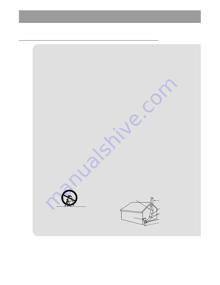
7. Accessories Carts and Stands
Do not place this product on a slippery or tilted surface, or on an
unstable cart, stand, tripod, bracket, or table. The product may
slide or fall, causing serious injury to a child or adult, and serious
damage to the product. Use only with a cart, stand, tripod, brack-
et, or table recommended by the manufacturer, or sold with the
product. Any mounting of the product should follow the manu-
facturer’s instructions, and should use a mounting accessory
recommended by the manufacturer.
8. Transporting Product
A product and cart combination should be moved with care.
Quick stops, excessive force, and uneven surfaces may cause
the product and cart combination to overturn.

9. Attachments
Do not use attachments not recommended by the product man-
ufacturer as they may cause hazards.
10. Ventilation
Slots and openings in the cabinet are provided for ventilation

and to ensure reliable operation of the product and to protect it
from overheating, and these openings must not be blocked or
covered. The openings should never be blocked by placing the
product on a bed, sofa, rug, or other similar surface. This prod-
uct should not be placed in a built-in installation such as a book-
case or rack unless proper ventilation is provided or the manu-
facturer’s instructions have been adhered to.
11. Power Sources
This product should be operated only from the type of power
source indicated on the marking label. If you are not sure of the
type of power supply to your home, consult your product dealer
or local power company. For products intended to operate from
battery power, or other sources, refer to the operating instruc-
tions.
12. Power-Cord Polarization
This product is equipped with a three-wire grounding type plug,
a plug having a third (grounding) pin. This plug will only fit into
the grounding-type power outlet. This is a safety feature. If you
are unable to insert the plug into the outlet, contact your electri-
cian to replace your obsolete outlet. Do not defeat the safety pur-
pose of the grounding-type plug.
13. Outdoor Antenna Grounding
If an outside antenna or cable system is connected to the prod-
uct, be sure the antenna or cable system is grounded so as to
provide some protection against voltage surges and built-up sta-
tic charges. Article 810 of the National Electrical Code (U.S.A.),
ANSI/ NFPA 70 provides information with regard to proper
grounding of the mast and supporting structure, grounding of the
lead-in wire to an antenna discharge unit, size of grounding con-
ductors, location of antenna-discharge unit, connection to
grounding electrodes, and requirements for the grounding elec-
trode. 

PORTABLE CART WARNING

Antenna Lead in Wire

Antenna Discharge Unit
(NEC Section 810-20)

Grounding Conductor
(NEC Section 810-21)

Ground Clamps

Power Service Grounding
Electrode System (NEC
Art 250, Part H)

Ground Clamp

Electric Service

Equipment

Example of Grounding According to National
Electrical Code Instructions

NEC - National Electrical Code

Содержание L30W36

Страница 1: ...Copyright 2003 Zenith Electronics Corporation Installation and Operating Guide Warranty Model Number L30W36 LCD AV MONITOR...

Страница 2: ...2 9 million individual cells It is common for a few defective cells to appear as minute colored dots on the screen as a result of the manufacturing process A tolerance of up to six defec tive cells h...

Страница 3: ...2 Checking Available Features 23 Sleep Timer Setting Sleep Timer 24 Picture Sound Auto Picture Control 25 Adjusting Picture Appearance 26 Auto Sound Control 27 Adjusting Sound Bass Treble Balance 28 S...

Страница 4: ...ent see pages 14 through 20 3 Install batteries in remote control See page 13 4 Turn monitor on See page 22 5 Choose on screen menu language See page 29 English is selected 6 Turn video source equipme...

Страница 5: ...erates uses and can radiate radio frequency energy and if not installed and used in accordance with the instructions may cause harmful interference to radio communications However there is no guarante...

Страница 6: ...ion to overturn 9 Attachments Do not use attachments not recommended by the product man ufacturer as they may cause hazards 10 Ventilation Slots and openings in the cabinet are provided for ventilatio...

Страница 7: ...u to dangerous voltage or other hazards Refer all servicing to qualified service personnel 20 Damage Requiring Service Unplug this product from the wall outlet and refer servicing to qualified service...

Страница 8: ...UT SELECT Front Panel Controls Main Power button INPUT SELECT button Power standby indicator Illuminates orange in stand by mode illuminates green when the Monitor is turned on Remote control sensor M...

Страница 9: ...PUT DIGITAL RGB INPUT RGB 1 INPUT PC DTV INPUT RS 232C INPUT CONTROL SERVICE DC OUTPUT DC 12V R L EXTERNAL SPEAKER 6 Back Panel Connection Panel Overview A V Input COMPONENT DVD DTV INPUT jacks S vide...

Страница 10: ...the Monitor 10 1 2 3 4 5 6 7 8 0 9 SLEEP INPUT SELECT POWER APC DASP ARC PIP ARC PIP TWIN PICTURE SWAP SUB INPUT MENU MUTE VOL VOL ENTER ZOOM ZOOM WIN SIZE WIN POSITION VOL PIP Refer to p 36 ARC Refe...

Страница 11: ...ound Special Features Misc Input Select Key on remote con trol Each press changes the source as shown below RGB2 COMPONENT RGB1 S VIDEO MUTE switches the sound on or off DASP Refer to p 27 PIP ARC Ref...

Страница 12: ...ECT POWER APC DASP ARC PIP ARC PIP TWIN PICTURE SWAP SUB INPUT MENU MUTE VOL VOL ENTER ZOOM ZOOM WIN SIZE WIN POSITION Remote Control Owner s Manual Alkaline Batteries DVI Computer DVI D Cable PC Audi...

Страница 13: ...and match with Install two 1 5V AAA alkaline batteries Don t mix used batteries with new batteries Notes for Using the Remote Control Make sure these are no objects between the remote control and its...

Страница 14: ...ght red If you have a mono VCR connect the audio cable from the VCR to the AUDIO L MONO input on the LCD Monitor If you connect an S VIDEO VCR to the S VIDEO input the picture quality is improved comp...

Страница 15: ...INPUT R L AUDIO RGB 2 INPUT DIGITAL RGB INPUT RGB 1 INPUT PC DTV INPUT RS 232C INPUT CONTROL SERVICE DC OUTPUT DC 12V Monitor Connections Panel To Watch VCR Use the INPUT SELECT button on the remote...

Страница 16: ...AV INPUT COMPONENT DVD DTV INPUT AC INPUT R L AUDIO RGB 2 INPUT DIGITAL RGB INPUT RGB 1 INPUT PC DTV INPUT RS 232C INPUT CONTROL SERVICE DC OUTPUT DC 12V To Watch Cable TV Programming Use the INPUT S...

Страница 17: ...yer DDR DC OUTPUT DC 12V To watch external AV source Use the INPUT SELECT on the monitor remote control to select VIDEO 1 Operate the corresponding external equip ment See external equipment operating...

Страница 18: ...utton on the monitor s remote control to select COMPONENT Turn on the DVD player and insert a DVD Follow instructions in the DVD player s owners manual Component Input Jacks Connect DVD player jacks t...

Страница 19: ...E R AUDIO L R AUDIO L Y PB R P DTV OUTPUT DC OUTPUT DC 12V DVI HDTV OUT Turn on the digital SET TOP BOX Refer to the owner s manual for the digital SET TOP BOX Use the INPUT SELECT button on the remot...

Страница 20: ...e audio cable from the PC to the Audio ports on the Monitor If your PC is equipped with a sound card adjust the sound output on the PC Set the display resolution of the PC to 1024X768 for the best pic...

Страница 21: ...RGB2 DVI Digital RGB modes If the graphic card on the PC does not output analog and digital RGB simultaneously connect either the RGB1 INPUT PC DTV INPUT or the RGB2 INPUT DIGITAL RGB INPUT to displa...

Страница 22: ...e Monitor or press the POWER or INPUT SELECT button on the remote control and then the Monitor will turn on If the Monitor is turned off with the remote control button Press the main ON OFF button on...

Страница 23: ...ed to adjust the selected menu option Press the MENU button to exit Use the remote control to make adjustments Select VIDEO input source SOUND SPECIAL PICTURE ADJ TWIN PIP PICTURE APC Contrast Brightn...

Страница 24: ...set setting time is changed as follows To release sleep time setting press the SLEEP button repeatedly to select 10 20 30 120 180 240 90 60 Tips To check remaining sleep time after setting press the S...

Страница 25: ...on Use the APC or UP DOWN buttons to select your desired picture appearance Each press of APC button or UP DOWN buttons changes the menu option as shown below You can also select Clear Soft or User in...

Страница 26: ...te adjustments and then press the ENTER button Use the UP DOWN buttons to select other menu options Press the MENU button and then use the UP DOWN button to select PICTURE menu Press the VOL G button...

Страница 27: ...ustment the Monitor automatically selects the appropriate audio tone levels based on the program content 1 Press the DASP button 2 Use the DASP or UP DOWN button to select a sound setup Each press of...

Страница 28: ...on to select the SOUND menu Press the VOL G button 2 Use the VOL buttons to make appropriate adjustments and then press the ENTER button Use the UP DOWN buttons to select other menu options MENU VOL V...

Страница 29: ...language Press the ENTER button to remove menu Press the MENU button and then use the UP DOWN button to select SPECIAL menu Press the VOL G button MENU VOL VOL ENTER Language Color TEMP R Adjust G Adj...

Страница 30: ...r desired color temperature and then press the ENTER button Use the UP DOWN button to select R Adjust G Adjust and B Adjust in the same way Press the VOL F button again to go back within menu MENU VOL...

Страница 31: ...event a permanent image burn in the picture will move a little every 10 minutes CAUTION The SCREEN SAVER function will help to prevent a permanent image burn in but it is still possible to permanently...

Страница 32: ...You can also select WIDE NORMAL or ZOOM in the PICTURE menu Each press of the ARC button selects WIDE NORMAL or ZOOM option WIDE NORMAL ZOOM Wide and Normal options are available in RGB1 PC and RGB2 m...

Страница 33: ...an zoom in on the image up to 50x Use the VOL buttons to select desired zoom in or out Press the MENU button and then use the UP DOWN button to select the PICTURE ADJ menu Press the VOL G button MENU...

Страница 34: ...ss the VOL G button MENU VOL VOL VOL VOL Initializing Reset to original setting PICTURE ADJ Auto Config ARC Main Zoom In Out Position Clock Adjust Phase Adjust Reset D E Move Position G F Prev Adjust...

Страница 35: ...Screen Option This function works in Video and S video modes Use this option to correct trembling or picture instability while viewing a video tape MENU VOL VOL ENTER PICTURE APC Contrast Brightness...

Страница 36: ...S video Video DVD 480i the PIP picture source is RGB1 RGB2 DTV more than 480p Press the PIP button PIP Selecting PIP Picture Size Press the WIN SIZE button to the PIP picture size menu WIN SIZE FGAdju...

Страница 37: ...ON button in PIP mode WIN POSITION Use the VOL F G button and UP DOWN button to move the picture Switch the Main and PIP Pictures Press the SWAP button in PIP mode SWAP RGB1 VIDEO VIDEO RGB1 RGB1 VIDE...

Страница 38: ...icture size with ZOOM button Reduce the Main Picture size with ZOOM button Zoom 25 F D E G A Pos Adj Exit Moving the Enlarged Main Picture Use the VOL F G button or UP DOWN button to change the positi...

Страница 39: ...OFF Selecting the Twin Picture Source VIDEO RGB1 Use the SUB INPUT button to select the Twin Picture source When the Main Picture source is RGB1 RGB2 DTV more than 480p the Twin Picture source is S vi...

Страница 40: ...ture mode WIN Size function doesn t work if there is no signal for Main Twin picture FGAdjust A Exit Window Size Twin Picture Feature TWIN PICTURE let you view different source inputs on your monitor...

Страница 41: ...justments Select RGB 1 input source PC Mode Features 2 Press the UP DOWN button Each press will cycle through the menus shown below SOUND SPECIAL PICTURE ADJ TWIN PIP PICTURE APC Contrast Brightness C...

Страница 42: ...nfig ARC Main Zoom In Out Position Clock Adjust Phase Adjust Reset D E Move Auto Config G F Prev To Set PICTURE ADJ Auto Config ARC Main Zoom In Out Position Clock Adjust Phase Adjust Reset OK 3 If th...

Страница 43: ...set Clock Adjust G 0 Clock 25 FG Adjust D E Move A Prev Horizontal Vertical position and CLOCK PHASE adjustment work in RGB1 PC mode and Horizontal Vertical position only work in RGB DTV mode 480p 720...

Страница 44: ...INPUT AC INPUT R L AUDIO RGB 2 INPUT DIGITAL RGB INPUT RGB 1 INPUT PC DTV INPUT RS 232C INPUT CONTROL SERVICE DC OUTPUT DC 12V Monitor Rear Connections Panel Connect the RS 232C serial connector input...

Страница 45: ...tton and then use the UP DOWN button to select SPECIAL menu Press the VOL G button 2 Use the VOL button to choose a monitor identification number ID and then press the ENTER button The Set ID adjustme...

Страница 46: ...Use a Crossed reverse cable The RS 232C input jack connection is used to control the Monitor s functions with an external control device NAME Command Command DATA 01 Power k a 0 1 02 Input Select k b...

Страница 47: ...ta x Error Acknowledgement The Monitor transmits ACK acknowledgement based on this format when receiving abnormal data from non viable functions or communication errors Data 01 illegal code This comma...

Страница 48: ...nd c G To adjust the screen format You can also adjust the screen format using the ARC button on remote control or in the Picture Adj menu Transmission Data 0 Wide screen 16 9 1 Normal screen 4 3 2 Fu...

Страница 49: ...64 Transmit as Hexadecimal code k k Set ID Data Cr Acknowledgement Data Min 0 Max 64 k Set ID OK Data X 12 OSD Select Command l G To select OSD On Screen Display on off Transmission Data 0 OSD off 1 O...

Страница 50: ...Data Cr Acknowledgement Data 0 Right down on screen 1 Left down on screen 2 Left up on screen 3 Right up on screen q Set ID OK Data X 15 PIP Size Command o G To select PIP size Transmission Data 0 No...

Страница 51: ...in 0 Max 64 Data Min 0 Max 64 Transmit as Hexadecimal code v Set ID OK Data X 22 G Adjust Command w G To adjust G adjust green color temperature Transmission k w Set ID Data Cr Acknowledgement Data Mi...

Страница 52: ...turn on your Monitor Cleaning the Cabinet To remove dirt or dust wipe the cabinet with a soft dry lint free cloth Please be sure not to use a wet cloth Extended Absence If you leave your Monitor dorm...

Страница 53: ...TURE menu and press the VOLUME G button See page 26 Increase the distance between the Monitor and the VCR Activate any function to restore the brightness of the picture If still picture is on the scre...

Страница 54: ...Please contact your service center if the picture has not appeared after five minutes Horizontal vertical bars or picture shaking Check for local interference such as an electrical appliance or power...

Страница 55: ...ecifications MODEL Width inches mm Height inches mm Depth inches mm Weight pounds kg Power requirement Resolution Colors L30W36 29 9 759 21 5 546 7 1 179 5 40 6 18 4 AC 100 240 60Hz 1280 x 768 Dot 16...

Страница 56: ...ng installation adjustment of user controls calibra tion maintenance or failure to maintain or separate system components and 2 Damages or operating problems that result from normal wear and tear misu...

Отзывы: