- 12 -
ADJUSTMENT INSTRUCTIONS
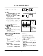
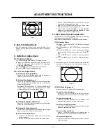
2. Select VP 7(AFC-ANGLE) and adjust the vertical slope.
3. Select VP 8(AFC-BOW) and adjust the left and right
crooked line on upper and lower side.
4. Select VP 9(PIN-AMP) and adjust until Pincushion
distortion disspears on left and right side.
5. Select VP 10, 11(UP-CORNERPIN, LO-CORNERPIN)
and adjust until pincushion distortion dispears on upper
and lower side of screen, respectively.
10. D/W Deflection Adjustment
Unnecesary
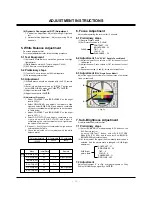
11. OSD position Adjustment
This adjustment should be performed only when there is
problem about the horizontal position of OSD.
(1) Enter into OSD adjustment mode by “INSTART” button on
the SVC Remote control and select OSD-Position mode
with CH
D
,
E
button. Adjust OSD horizontal position by
VOL
F
,
G
button. (OSD POSITION Initial data : 9)
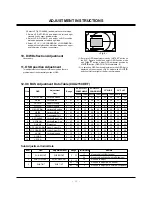
(2) In selecting OSD Position adjustment mode OSD bar is
displayed on the screen as <Fig. 6> Adjust with VOL
F
,
G
button until left and right of the bar is symmetrized.
<Fig. 6>
12. IIC BUS Adjustment Data Table(CXA2150 DEF)
Sub Adjustment Initial Data
0
1
2
3
4
5
6
7
8
9
10
11
12
13
14
3
1
2
SUB-TINT
SUB-BRIGHT
SUB-CONTRAST
SUB TINT
-24
~
39
-23
~
40
SUB BRIGHT
0
~
63
SUB CONTRAST
0
~
15
V-POSITION
V-SIZE
UP-VLIN
LO-VLIN
H-POSITION
H-SIZE
PIN-PH
AFC-ANGLE
AFC-BOW
PIN-AMP
UP-CORNER PIN
LO-CORNER PIN
V-VLIN
S-CORR
V-SCRO
17
20
10
0
0
Need to Adjust(USA/Canada)
Need to Adjust(Latin America/Philippines)
No need to Adjust
No need to Adjust(USA/Canada)
No need to Adjust(Latin America/Philippines)
0
~
63
0
~
63
0
~
15
0
~
15
0
~
63
0
~
63
0
~
63
0
~
63
0
~
63
0
~
63
0
~
63
0
~
63
0
~
15
0
~
15
0
~
63
30
31
3
4
19
23
42
30
32
24
38
37
5
3
27
30
30
2
3
30
34
35
29
31
33
35
36
5
3
24
43
24
3
3
24
25
40
28
29
23
28
28
5
5
27
36
24
3
3
34
38
34
27
32
31
37
37
5
5
24
23
27
1
5
23
28
26
30
34
32
39
34
5
2
34
26
28
1
5
32
42
25
30
34
40
39
34
5
2
28
30
31
3
4
19
23
42
30
32
24
38
37
5
3
27
30
30
2
3
30
34
35
29
31
33
35
36
5
3
24
Vertical Position
Vertical Size
Upper Linearity
Lower Linearity
Horizontal Position
Horizontal Size
Trapezoidal Corr.
Vertical Slope Corr.
Vertical Skew Corr.
Pincushion
Upper Corner Pin
Lower Corner Pin
Vertical Linearity
Item
OSD
Adjustment
Item
Range
Item
OSD
Adjustment Item
Range
Initial Data
Remark
RU-29FC32/51
GOMEZ,SINGLE
RP-29FC40P
DOUBLE/SINGLE
32” WIDE
34” FLAT
480I/P
1080I
480I/P
1080I
480I/P
1080I
480I/P
1080I
Содержание C30W46
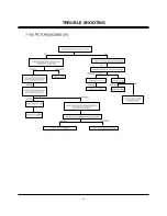
Страница 17: ...17 TROUBLE SHOOTING...
Страница 18: ...18 TROUBLE SHOOTING...
Страница 19: ...19 TROUBLE SHOOTING...
Страница 20: ...20 TROUBLE SHOOTING...
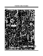
Страница 21: ...21 PRINTED CIRCUIT BOARD MAIN...
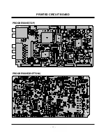
Страница 22: ...22 PRINTED CIRCUIT BOARD PROGRESSIVE TOP PROGRESSIVE BOTTOM...
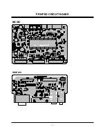
Страница 23: ...23 MICOM PRINTED CIRCUIT BOARD SIDE A V...
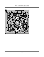
Страница 24: ...24 CPT PRINTED CIRCUIT BOARD...
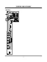
Страница 25: ...25 CONTROL PRINTED CIRCUIT BOARD...
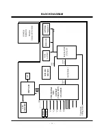
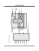
Страница 27: ...27 Option BLOCK DIAGRAM...
Страница 38: ......
Страница 39: ......
Страница 40: ......


