background image

Zenith Autoboil - Installation & Operating Instructions - 804545NZ - 03.17 v1.00


Page 3 of 24

Read These Warnings First

Please read all installation requirements, installation procedures 

and precautions before installing any Zenith Autoboil instant boiling 

water heater.
Never attempt to install any Zenith Autoboil instant boiling water 

heater without reading all of the applicable instructions.
In some hard water areas where mineral scale accumulation in 

the boiling chamber of the Zenith Autoboil may become a problem, 

consideration should be given to the maintenance required. A 

suitable form of water treatment may be necessary.
The cold water supply to this appliance must be potable and fall 

within your local authority’s guidelines.
All plumbing connections must be made in accordance with local 

regulations.
The Zenith Autoboil instant boiling water heater is not intended for 

use by young children or infirm people without supervision. 
Young children should be prevented from having access to ensure 

that they are not able to use or play with the heater.  
This appliance must be earthed. If the power supply cord is damaged 

it must be replaced by a Zenith authorised agent or a qualified 

electrician. 
Do not remove the cover of the heater under any circumstances 

without first isolating the heater from the power supply.
Do not use strong, corrosive or abrasive cleaners to clean the case 

of the heater.
Frost protection: If this heater is located where ambient air 

temperature could fall below 5ºC when the heater is not in use, do 

not turn off the appliance electrically. This safeguide does not offer 

the same protection to the connecting pipework and fittings.
The ambient temperatures this unit must operate within is 5ºC - 

50ºC.
This heater is intended only for indoor use and should never be 

installed outdoors or be exposed to the elements of nature.
This unit must not be positioned in an area that may be cleaned by a 

water jet. This unit must not be cleaned by a water jet.

Before installing, ensure that the following are available:
a)  Sufficient space to position the heater so there is at least 100 mm  

  clearance above the heater for service access, 150 mm to its left 

and 

20 mm to its right – the tap outlet must be positioned at least 

300 mm above a draining board or drip tray.

b)  Standard 220- 240 volt power cable positioned as shown on the 

paper mounting template for connection from the rear of the 

heater to the terminal block within the heater, OR a standard 10 

amp 220- 240 volt power outlet on the wall within 1500 mm of the 

heater. This switch must provide all-pole disconnection and a 

contact separation of at least 3 mm installed in accordance with 

wiring rules, see Step 3 - 3.3). 

Installation Requirements

Содержание Autoboil 3

Страница 1: ...3 Litre White 303651 Zenith Autoboil 3 Litre Stainless Steel 305652 Zenith Autoboil 5 Litre White 305651 Zenith Autoboil 5 Litre Stainless Steel 307652 Zenith Autoboil 7 5 Litre White 307651 Zenith Au...

Страница 2: ...ons including children with reduced physical sensory or mental capabilities or lack of expe rience and knowledge unless they have been given supervision or instruction concerning use of the appliance...

Страница 3: ...ances without first isolating the heater from the power supply Do not use strong corrosive or abrasive cleaners to clean the case of the heater Frost protection If this heater is located where ambient...

Страница 4: ...sed plumbing and or electrical connections Concealed connections are preferred for superior appearance Step 1 Positioning Position the heater so the tap will drain on to a draining board or drip tray...

Страница 5: ...t the operation of the heater It is recommended that the heater be installed with a stop cock which allows it to be isolated from the mains supply for servicing Water pressure requirements Minimum 70...

Страница 6: ...gh the rear access opening to the green terminal block on the PCB Check that the earth is connected through the PCB to the chassis with an ohm meter Warning Do not connect both options It is essential...

Страница 7: ...ck nut Step 6 Installing Filter NOTE For safe operation the filter cartridge should be replaced every 6 12 months or earlier if you notice a persistent reduction in water pressure from the appliance o...

Страница 8: ...the tap push the lever backwards into the locked open position fig 2 and allow the tank to fill until water flows from the tap outlet 6 Once the water is available from the tap turn off the mains wat...

Страница 9: ...Understanding Icons and Buttons Move to the next item able to be highlighted Move to the previous item able to be highlighted Confirm menu selection Move to the previous menu Perform one of 3 functio...

Страница 10: ...the sleep mode settings menu Filter Indication Days remaining of filter life Shown red filter needs replacement Sleep Mode Indication Unit will enter sleep mode at the time shown Unit will enter sleep...

Страница 11: ...age 11 of 24 3 Settings Menu Select on the home screen to navigate to the main menu Choose Settings and select Choose an option and select 2 3 Sleep Override Mode Awake time remaining Unit will return...

Страница 12: ...re quire boiling calibration to prevent excessive steam release or high energy usage see section 4 2 3 3 Settings Sleep Modes From the settings menu choose Sleep Modes and select Choose Sleep Trigger...

Страница 13: ...ultaneously Adjust on off timer settings for the 2 weekend days simultane ously Adjust on off timer settings for the 7 days separately Weekdays Weekends Individual Days 3 3 3 Timer Settings Individual...

Страница 14: ...the filter shown on this menu and on the home screen are based on these 2 parameters This action will reset the filter usage counter A re minder is shown to flush the new filter before doing this see...

Страница 15: ...on environment may have changed requiring recalibration of the boiling point Incorrect boiling calibration points may cause excessive steam vent releases or increased energy usage Boiling calibration...

Страница 16: ...e install menu choose Product 5 2 Info Current Fault From the info menu choose Current Fault 6 Service Menu Note The service menu is used by technicians only for diagnostic purposes Menu Operation 5 I...

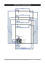
Страница 17: ...Zenith Autoboil Installation Operating Instructions 804545NZ 03 17 v1 00 Page 17 of 24 Wall Mounting Template Dimensions ROG QOHW 9HQW WHUQDO 3OXPELQJ OHFWULFDO LULQJ QWHUQDO 3OXPELQJ 3RVLWLRQLQJ SLQ...

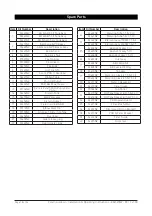
Страница 18: ...3118NZ Elbow Stem 1 4 19 90100NZ Grommet Cistern to Tank 20 94458NZ Overload 21 94459NZ Side release plug 22 94460NZ Seal transfer tube Item Kit Number Description 23 94483NZ Metering Tube 1 5 3 Ltr 9...

Страница 19: ...Zenith Autoboil Installation Operating Instructions 804545NZ 03 17 v1 00 Page 19 of 24 Exploded View Diagram...

Страница 20: ...on Water isolating valve turned off Blocked filter blocked meter tube blocked strainer jammed ball valve assembly Check filter flush valve position see Step 7 page 8 Check filter is inserted correctly...

Страница 21: ...notice a persistent reduction in water pressure from the appliance or an unpleasant taste or odour in the water To Replace Filter Turn the filter anti clockwise fig 1 and pull the cartridge down fig...

Страница 22: ...eaning Cleaning Case Do not use strong corrosive spray or abrasive cleaners Clean the case with a soft cloth or sponge and mild soapy water Dispose of the filter cartridge responsibly Use only Zenith...

Страница 23: ...Zenith Autoboil Installation Operating Instructions 804545NZ 03 17 v1 00 Page 23 of 24 NOTES...

Страница 24: ...one of continuous product improvement changes to specifications may be made without prior notice Images in this booklet have been modified and may not be true representations of the finished goods Th...

Отзывы: