background image

6

11.   Connect the main connection cable (No. 2) of the 

ZENEC system (No. 1) to the two radio plugs on 

the vehicle.


 Depending on your vehicle, you must use either 

the 20-pin (No. 3) or the 28-pin connector (No. 4) 

to operate the AUX connector and the steering 

wheel remote control. You must connect these to 

the main connection cable.


 The reverse gear signal is supported only by the 

28-pin connector (No. 4). If your vehicle is fitted 

with a 20-pin connector (No. 3), you need to use 

a gauge to search for the reverse gear signal and 

connect it directly to the main connection cable 

(No. 2).


 If you cannot find an ISO antenna plug in your 

vehicle, it is most likely that your vehicle is using 

a special Toyota antenna plug. If this is the case, 

the set includes a FM ISO antenna interface (No. 

6) which you can simply connect to the original 

unit. If the antenna is active, you must also con-

nect the blue phantom power cable to the main 

connection cable (No. 2).

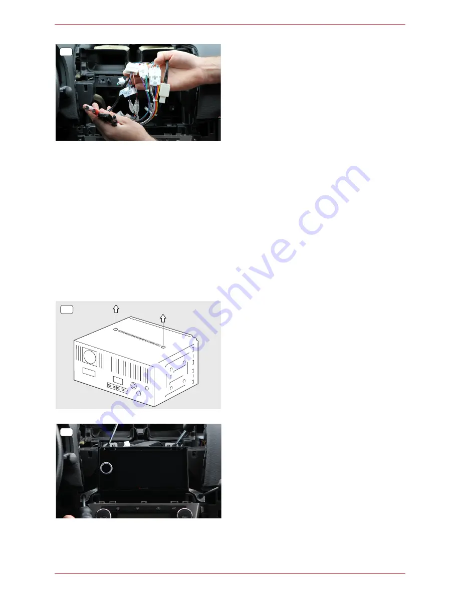
12.   Remove both screws from the transport lock 

prior to installing the ZENEC system (No. 1).

13.   (No picture) 

Connect all cables previously installed in the 

radio bay to the ZENEC system (No. 1).

14.   Carefully route the various connection cables of 

the ZENEC system in the lower section of the 

radio bay. Then slide the ZENEC system careful-

ly into the radio bay by applying controlled force. 

Screw it back into position with the four Phillips 

(PH2) or hex (10mm) screws.

11

14

12

Содержание Z-E6150

Страница 1: ...1 Z E6150 INSTALLATION MANUAL EN ...

Страница 2: ...he following section shows how to tell the difference on the basis of a Toyota Avensis 3G Type T27 Manufacturer Model Model type Model year Toyota Auris 1G Type E150 2006 2012 Toyota Avensis 1G Type T22 2001 2003 Toyota Avensis 2G Type T25 2003 2009 Toyota Avensis 3G Type T27 2009 2015 Toyota Avensis Verso 2001 2005 Toyota Camry 5G Type XV30 2001 2006 Toyota Celica 7G Type T23 1999 2005 Toyota Cor...

Страница 3: ...with the ZENEC system ZENEC system software updates are installed using a USB data stick You must therefore ensure that the USB connection on the ZENEC system remains accessible during installation installation of USB extension If you have any queries or problems with the ZENEC system please contact the retailer where you purchased it SUPPLIED ITEMS No Item Quantity 1 ZENEC system 1 2 Main power c...

Страница 4: ...he cen tre console out of its fixture as shown in the diagram You require a plastic lever tool for this step 2 Lever the plastic cover on the left of the centre console out of its fixture as shown in the dia gram You require a plastic lever tool for this step 3 To begin with lever the radio cover air vent noz zle upwards out of its fixture Slide the lever tool around the plastic frame once from ri...

Страница 5: ... affected by unwanted shielding of metallic vehicle parts thermal insulation glazing etc Then route the connection cable into the radio bay 9 No picture If you have purchased the optional external Blue tooth microphone N ZENC MIC install it now and then insert the connection cable into the radio bay Depending on your preference and whether you select an internal or external microphone the micropho...

Страница 6: ...tenna plug in your vehicle it is most likely that your vehicle is using a special Toyota antenna plug If this is the case the set includes a FM ISO antenna interface No 6 which you can simply connect to the original unit If the antenna is active you must also con nect the blue phantom power cable to the main connection cable No 2 12 Remove both screws from the transport lock prior to installing th...

Страница 7: ...nd right of the centre console NOTE Ensure that all the plugs on the rear of the unit have sufficient clearance and are not kinked Any plug in connections which do not have a securing mechanism must also be secured with insulating tape STARTUP Finally carry out a general function test and perform the basic settings and vehicle specific settings steering wheel remote control etc Also make sure that...

Страница 8: ... B4 Video IN B5 AUX IN L B6 AUX IN R B7 Line Out Rear L B8 Line Out Rear R B9 Line Out Front L B10 Line Out Front R B11 Line Out Sub Woofer B12 Line Out Sub Woofer B13 MIC B14 Front Camera 12V max 300mA B15 IR IN B16 GND B17 GND B18 Rear Camera 12V max 300mA B19 N A B20 N A B21 N A B22 N A B23 N A B24 N A B1 Speaker Front Right B2 Speaker Front Left B3 KL 15 Switched 12V PWR B4 KL 30 Constant 12V ...

Страница 9: ...B 1 USB 2 HDMI 28 Pin 20 Pin P ANT B C AUX IN R AUX IN L AUX IN R AUX IN L Rev Analog Wheel KEY KEY1 KEY2 GND B13 B12 B11 B10 B9 B8 B7 B6 B5 B4 B3 B2 B1 B15 B14 B17 B16 B18 E or D con nection cable depends on the vehicle ...

Страница 10: ...ical modifications excepted No liability for printing errors Copyright 2017 RevA copy deadline Q4 2017 English ZENEC Bohrturmweg 1 CH 5330 Bad Zurzach Schweiz Switzerland Mail support zenec com www zenec com ...

Отзывы: