Installation Instructions
Please read these installation instructions before starting work.
1 - 7
8 - 11
12 - 19
1
2
3
5
4
6
7
9
8
10
ø102mm
11
13
14
15
17
16
12
ø120mm
B
D
C
A
19
18
WARNING:
• ISOLATE THE FAN FROM THE MAINS SUPPLY BEFORE CARRYING OUT
WORK OF ANY KIND INCLUDING ALTERING THE TIMER OVERRUN.
• This appliance can be used by children aged from 8 years and above and
persons with reduced physical, sensory or mental capabilities or lack of
experience and knowledge if they have been given supervision or instruction
concerning use of the appliance in safe way and understand the hazards
involved. Children shall not play with the appliance.
• The light kit must be used in conjunction with a ventilation fan which
produces a minimum air movement of 54m
3
/h through the light assembly.
• Where an open-flued oil or gas-fuelled appliance is installed, precautions
must be taken to avoid a back-flow of gases into the room.
• The units should not be sited where it would be subject to a direct source of
heat in excess of 40°C.
• Once fitted into ceiling void or loft space do not cover light body, fan or LED
Driver with any insulating materials.
• Minimum void height when fitting into ceiling space and minimum distance
for light is 200mm.
• Observe appropriate safety precautions if working on steps or ladders. Wear
eye protection when breaking out wall materials etc.
• Always isolate fan from mains supply before cleaning. Do not use solvents to
clean this fan. Cleaning and user maintenance shall not be made by
children without supervision.
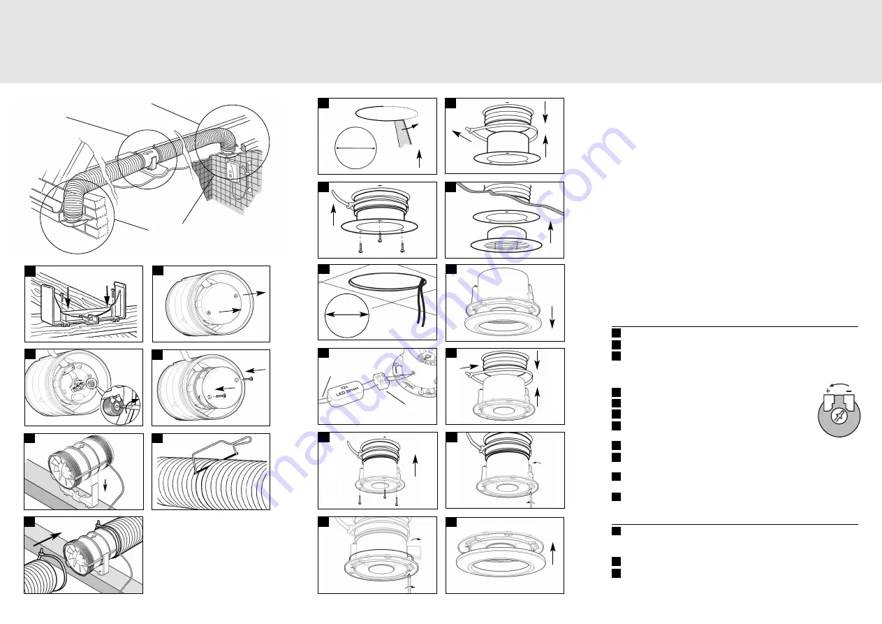
In-line Mounting
1
Secure the mounting foot supplied to a suitable roof beam or similar.
2
Remove 2 screws from fan motor cover and remove from fan body.
3
Insert cable through cable entry point on fan body and secure with clamp.
For timer model set the timer with a flat blade screwdriver. The timer is
adjustable between 2 and 30 minutes. It is set at midpoint. Note: Switch off
the mains electricity before adjusting controls.
4
Re-assemble using 2 screws to fit PCB cover to fan body.
5
Clip the fan body into the mounting foot.
6
Cut the ducting.
7
Place flexible ducting over the spigot of both ends of the fan
body. Fit ducting to spigot using ties.
8
Cut holes in ceiling and external soffit to take the grille body diameter.
9
Draw ducting through holes in ceiling and soffit, fit ducting to spigot using
ties.
10
Secure louvre body to ceiling and also to soffit. Fix with screws & wall
plugs as required.
11
Clip the louvre to the grille body.
Optional Light Fitting
12
Cut a hole in the ceiling of the room where the light will be installed and
thread through low voltage cables from LED Driver.
A
= 12V LED Driver cables
13
Unclip internal grille from light unit.
14
Wire the unit according to model diagram.
B
= From Mains Supply
C
= 12 Volt LED Driver
D
= Pre-wired terminal block


