4 - EN
EN - 5
5 Installation
First follow the installation instructions given in
this document. Do not:
�
mount the ducting,
�
connect the water batteries,
�
connect the power supply,
before finishing the instructions given in this
document.
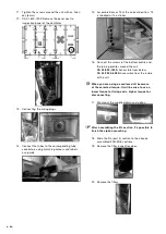
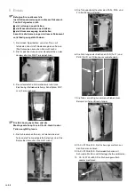
1. Remove the two locking bolts of all the doors with
missing plastic cover caps. (You do not need the
bolts again.)
2. Remove the inspection door in front of the main
PCB at the front side of the PHE part.
3. Remove the required information from inside such
as the drawing, manual, wiring diagram, DOP etc.
Take note of the drawing and read the manual for
mounting a CA XL unit in 3 parts carefully.
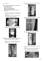
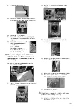
4. Remove the screws fixing the three parts to the
transport pallets. (You do not need the screws
again.)
5. Remove the transport pallets below the FAN, PHE
and FIL sections.
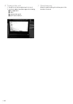
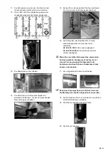
6. Pre-treated the seals of the FAN (Part 1) and PHE
(Part 2) sections with silicon spray.
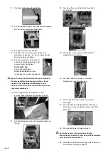
7. Slide the parts carefully together (for example
using a crowbar).
8. CA XL 2200-6000: Remove the lock nuts from the
frames.
9. CA XL 2200-6000: Connect the two frames with a
bolt nut and washer assembly to each other.
10. CA XL 2200-6000: Assembling the lock nuts
again.


