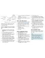
1. Insert one end of an Ethernet cable to the
Data/IN port
on the PoE injector as figured
above.
2. Insert the other end to the assigned LAN
port on your PC as figured above.
3. From your computer, go to Start > Settings >
Network Connections or Start > Control
Panel > Network Connections.
4. When the Network Connections window
appears, right-click the icon for Local Area
Connection, and then click select Properties.
5. Select Internet Protocol (TCP/IP) from the
scrolling list, and then click Properties.
6. Select Use the following IP address option (if
it is not already selected), and then make
the following entries:
STEP 3: LOG INTO THE AP
1. On your PC, open a Web browser window.
2. In the browser, type
https://192.168.1.1
and press <Enter> to connect to the AP.
3. When a security alert dialog box appears,
click OK/Yes to proceed.
4. When the login page appears, enter the
following:
• Username: admin
• Password: password
5. Click Login.
STEP 4: CONFIGURE THE AP
1. On the Web interface menu, click
Advanced Settings.
2. Select Wireless Mode:
FAT AP
.
3. Select
DHCP Client
to obtain an IP address
from the DHCP server automatically, or
select
STATIC
to enter the values manually.
Click
Apply
to save changes.
4. Go to RF Configure > Wireless Settings.
(For dual band 5G setting, select Card 2
first then go to RF Configure > Wireless
Settings.)
5. Select your location from Country/Region.
Click
Apply
to save the changes.
STEP 2: CONNECT THE AP TO YOUR
PC
6. Select a clean channel.
7. Go to RF Configure > Security Profile
8. Select a profile (eg. #1) , then click
Edit
.
9. Type the name of the network in the SSID
field.
10. Enable authentication and encryption as
needed. Click
Apply
to save the changes.
11. Repeat Steps 8-9 for each Profile #
interface that you want to enable.
12. Click
Logout
to exit the Web interface.
13. Disconnect the AP’s power adapter from
the power outlet (or disconnect the PoE
cable).
14. Move the AP to its permanent location
(accessible to both power source and
network connections).
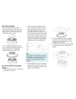
STEP 5: MOUNT THE AP
The ZAP-680 can be mounted to a ceiling or
wall using the supplied mounting brackets
and screws.
Alternatively, connect LAN1/PoE of the Access
Point to a PoE switch for both power and
network connectivity.
• IP address: Any address in the 192.168.1.x
network
• Subnet mask: 255.255.255.0
7. Click OK to save your changes, and exit the
dialog box.
Note:
Access points with integrated antennas
perform best when the access point is
mounted on horizontal surfaces such as a
ceiling. For smaller areas such as
conference rooms or hotel rooms, the unit
may be wall mounted using wall anchors or
screws.


