


12
b) Pilot drill the wall using an 8 mm drill and fix the splashback using the 8 mm rawl plugs
and screws supplied.
c) If the fixing holes in the bottom of the splashback are not to be used to secure the
splashback to the wall the installer should ensure that the bottom edge is tucked down behind
the rear of the worktop.
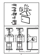
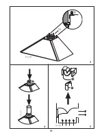
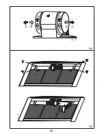
4.2 - Fixing the canopy hood (fig. 3)
1 - Adjust the two screws
V
(on the canopy connection points) to approximately half way.
2 - Hook the rear of the canopy to the wall bracket
1
, after anchoring the latter to the wall.
3 - Turn the screws
V
to adjust the canopy vertically and level it horizontally
.
4 - Fit and lock the central fixing screw
V1
(provided) to lock the canopy in place.
4.3 - Electrical connection and working test
1 - The safety measures 3.2, 3.3 and 3.4 of paragrapf 3 are to be strictly observed.
2 - Once the electrical connection has been completed, check that worktop illumination, motor
and speed work properly.
4.4 - Ducting or Recirculation fitting
1 - Ducting fitting
a) The cooker hood can be ducted to the outside using either rigid or flexible fire retardant
ducting of 120 or 150 mm. The choice is left to the installer. When 120 mm ducting is to be
used it will be necessary to install the reduction flange item
A
on the air outlet
fig. 4
.
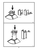
b) The installer should provide suitable ducting and sealing material for the installation. The
cooker hood can also be ducted to the outside through one of the rectangular openings
located in either side of the lower section of the chimney stack. In this case the deflector (item
D
) should be fitted into the spigot (item
R
) to close the aperture which is not used
(fig. 5)
.
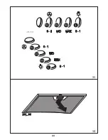
c) If the hood is provided with the charcoal filters fitted, the filters should be removed (see
paragraph 3.3 2 part 2
a
).
2 - Recirculation fitting
a) The filtered air is returned to the room through the two side grilles on U-shaped lower
section
I
, which are either formed in the metal itself (bottom position
fig. 6
), or as a plastic
insert, and have two different heights to deal with different needs (bottom position
fig. 6
, top
position
fig. 7
).
b) Lower position
(fig. 6)
: fit the recirculation spigot item
R
into the round outlet on top of
the canopy while pressing down on the spigot until it snaps into position.
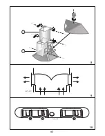
c) Upper position
(fig. 7)
: fit the additional spigot, item
P,
into the round outlet on top of the
canopy while pressing down on the spigot until it snaps into position. Then fit the
recirculation spigot
R
into the top of the spigot , item
P
, and install the charcoal filters inside
the canopy as instructed in paragraph 3.3 2 part 2
a
).
d)Chimney hood with grilles.
Nota:
The two venting grilles must not be fitted into the
chimney stack until the chimney stack has been installed onto the wall above the canopy.
4.5 - Fitting the telescopic chimney stack (fig. 8)
a) Fit the two plastic supports provided to the top part of the hood.
b) To fit the upper section item
S
first expand the chimney slightly to allow it to fit over the wall
brackets (item
2 fig. 1
) and then secure the upper section using the 4 screws supplied.
c) The lower section item
I
of the chimney stack should be fitted between the lower bracket
2
and the wall. Fix the U-shaped section to the plastic supports, using two of the screws provided
in the bag of accessories.
Содержание ZHC 915
Страница 11: ...40 b a 2 1 2 1 243_A02 X 115 140 d 915 min 650 min 265 40 X 115 140 d H 265 40 H B B 1 2...
Страница 12: ...41 3 4 5...
Страница 13: ...42 222 6 7...
Страница 14: ...43 10 9 8...
Страница 15: ...44 11 12...
Страница 16: ...45 13 a c b...
Страница 17: ...46 14 15...
Страница 18: ...47 16 17...