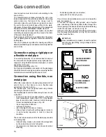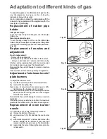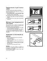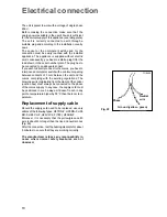
4
Using the cooker hob
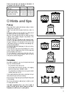
Control knobs on the gas hob
The knobs for using the gas hob of the cooker are found
on the control panel. The regulation knobs hould be
turned in anti-clockwise direction until the small flame
symbol, and vice-versa for the larger symbol.
No gas supply
Maximum gas supply
Minimum gas supply
Ignition of hob burners
To ignite a burner, before positioning the saucepan,
proceed as follows:
Manual ignition
- hold a flame near the burner, then turn the
corresponding knob in an anticlockwise direction to
the maximum position;
- upon ignition regulate the flame as required.
Models provided with electric ignition:
- push the ignition push button marked by a little spark;
- push the corresponding knob in completely and turn
in an anticlockwise direction to the maximum position;
- upon ignition regulate the flame as required.
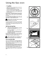
- In models provided with a
safety device
(fig. 1-a,
D
),
the control knob must be pressed in for approximately
5 seconds
until the safety valve automatically keeps
the flame lit.
If after a few attempts the burner does not ignite, check
that the burner cap and crown (fig.1) are correctly
positioned.
To interrupt the supply of gas, turn the knob in a
clockwise direction to the position "
l
".
During cooking, when using fats or oils, take
particular care as they can, when over-
heated, self-ignite.
When using the triple-crown burner, place
the special grid on the pan support (fig.2-a).
When using the auxiliary burner (with pans
having a diameter equal or higher than
50mm), place the special grid (provided only
in some models) on the pan support, as
shown in fig.2-b.
Triple-crown burner
In models provided with triple-crown burner,
always ignite the burner before putting the
pans on.
If after a few attempts the burner does not ignite, check
that the burner cap and crown are correctly positioned
(see fig. 1-b).
Control knob for the hotplates
Some models are equipped with hotplates. The
hotplates control knob (Fig.3) can be adjusted on four
different positions, according to your cooking needs,
from maximun heat (position 4) to minimum heat
(position 1).
Fig. 2-a
F
Fig. 3
0
1
2
3
4
FO 2193
Fig. 1-a
FO 0204
A
- Burner Cap
B
- Burner crown
C
-Spark generator
D
- Thermocouple
Fig. 1-b
Fig. 2-b
Содержание Gas and mixed fuel cookers
Страница 1: ...INSTRUCTION BOOKLET GAS AND MIXED FUEL COOKERS ...
Страница 20: ...35669 8003 02 01 Grafiche MDM Forlì ...


