
44
En
g
li
s
h
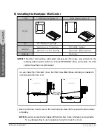
8. Ins
tall
a
t
io
n Gui
d
e
TNN 500AF
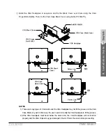
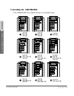
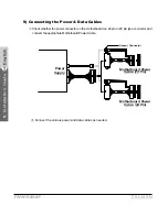
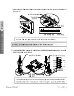
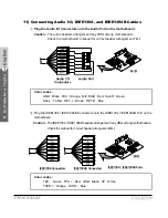
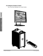
11) Connecting Audio I/O, IEEE1394, and IEEE1394B Cables
①
Plug the Audio I/O Connectors onto the Audio Port on the motherboard.
Caution :
The audio headers arrangement may differ among motherboards.
Check the motherboard’s manual for correct header arrangement First.
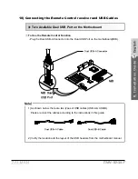
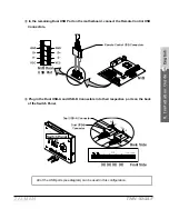
②
Plug the IEEE1394 / IEEE1394B Connectors onto the IEEE1394 / IEEE1394B Port on the
motherboard.
Caution :
The IEEE1394 / IEEE1394B headers arrangement may differ among motherboards.
Check the manual for correct header arrangement first.
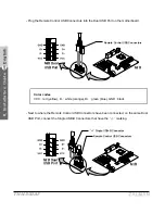
Color codes :
GND : Black, MIC : Orange, MIC BIAS : Red, Spk-R : Green,
Spk-L : Yellow, RET-L : Brown, RET-R : Blue
Color codes :
TPA - : Green, TPA + : Red, GND : Black, VP : White,
TAPB + : Orange, TAPB - : Blue
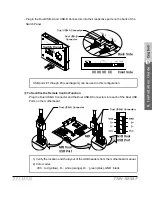
Audio I/O
Connectors
Audio Port
M/B
IEEE1394 Connectors
IEEE1394B Connectors
IEEE1394 / IEEE1394B Ports
M/B