ZALMAN TNN 500AF Скачать руководство пользователя страница 43

42

En

g

li

s

h

8. Ins

tall

a

t

io

n Gui

d

e

TNN 500AF

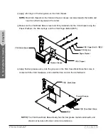
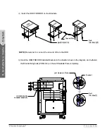
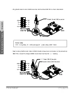
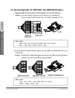
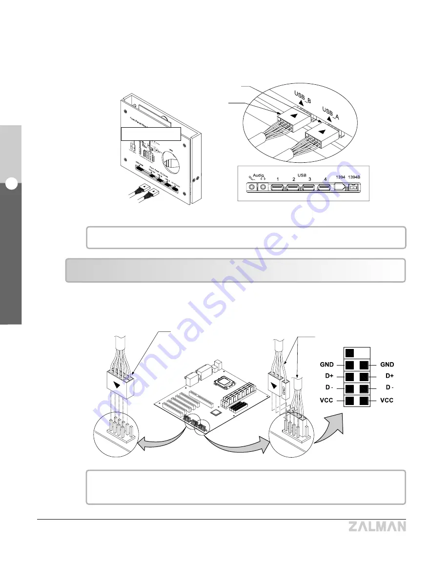
- Plug in the Dual USB-A and USB-B Connectors into their respective  ports on the back of the 

Switch Panel.

All of the USB ports (see diagram) can be used in this configuration.

Dual USB-A Connector

Dual USB-B  

Connector

Switch Panel

Back Side

(0) (0) (0) (0) 

Front Side

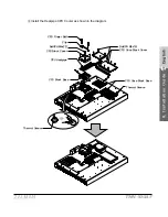
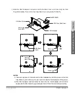
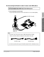
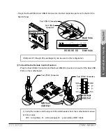
Plug the Dual USB-A Connector and the Dual USB-B Connectors into each of the Dual

USB Ports on the motherboard.

M/B Dual 

USB Port

M/B Dual 

USB Port

M/B

Dual USB-A Connector

Dual USB-B Connectors

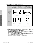
1) Verify the location and the layout of the USB headers from the motherboard manual.

2) 

Color codes :

VCC : red (yellow), D- : white (orange), D+ : green (blue), GND : black
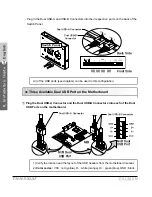
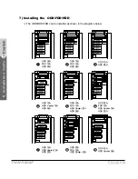
Three Available Dual USB Port on the Motherboard 

Содержание TNN 500AF

Страница 1: ...For other language versions please visit our website...

Страница 2: ...English English Edition www zalman co kr www zalmanusa com Please read before installation Visit our website and watch the TNN500AF installation video first to make your installation easier...

Страница 3: ...uting TNN 500AF is the ultimate answer to every computer user s dream of creating a silent computing environment with total system stability Contents 1 Safety Notices 2 Features 3 Patents 4 Components...

Страница 4: ...the system 8 If this unit is to be transported a long distance place it in the original packing box or a custom made hard case 9 Do not drop or expose this unit to shock while it is in transit 10 Sto...

Страница 5: ...Even the HDD noise is blocked out by the sturdy aluminum plates 5 to 7mm thick achieving completely silent computing 2 Stability No Fans in the System The majority of heat generated inside the system...

Страница 6: ...to the heatsink plate through 3 heatpipes each 6 millimeters in diameter The three heatpipes can transfer up to 75W of heat from the VGA chipset sufficient for the hottest VGA cards on the market Nor...

Страница 7: ...The TNN Power Supply extends the output voltage sensors up to the motherboard connection for 3 3V 5V and 12V rails to prevent this enhancing output voltage accuracy and assuring system stability Data...

Страница 8: ...se Four casters wheels withstand up to four metric tons of weight in total and have skid prevention height adjustment features built in The case is structured to easily house up to two ODDs and five H...

Страница 9: ...8 English 2 Features TNN 500AF Test Results AMD AMD64 Athlon64 System Thermal Test Room Temperature 28 TNN 500AF AMD System Conventional AMD System Fan Speed at Full Load Power Consumption Test...

Страница 10: ...00AF Configuration of Systems for Testing Testing Equipment and Programs CPU Loading Program CPU Burn High Measurement Instrument Personal Daq 56 Iotech Inc KIKUSUI PCR 1000L Temperature Measurement P...

Страница 11: ...10 English 2 Features TNN 500AF Fan Speed at Full Load Intel P4 Prescott System Thermal Test Room Temperature 25 Power Consumption Test TNN 500AF Intel System Conventional Intel System...

Страница 12: ...the Prescott Processor Rev 1 2 Measurement Instrument Personal Daq 56 Iotech Inc KIKUSUI PCR 1000L Temperature Measurement Program DaqView Iotech Inc Caution 1 If the CPU has a higher Thermal Design...

Страница 13: ...0AF Right Heatsink Plate Front Door Swithch Front Aux Panel Top Plate Cover CPU Cooler Parts Power Inlet Bottom Plate ODD FDD HDD HDD Cooler Brackets Fanless Power Supply Left Heatsink Plate Rear Plat...

Страница 14: ...2 AMD64 Finger Bolts 6 32X40 Two 2 AMD64 Nipples Two 2 Socket 775 Finger Bolts M3X49 Four 4 PH M3X22 Bolts 2 Heatpipe VGA Cooler Parts One 1 Bag VGA Block Base A B Cover one 1 Each Four 4 VGA Finger B...

Страница 15: ...erboard Bolts One 1 Bag Ten 10 PWH M3X5 Bolts 9 Thermal Grease 2 5 ml 10 ATA 133 Cable One 1 Bag One 1 ATA 133 Cable 11 Power Cord One 1 Bag One 1 Power Cord 12 Latch Key One 1 Bag Two 2 Latch Keys 14...

Страница 16: ...ST be installed and operated at 1000 1200rpm and Rear mount Thermal Blocks ZM RTB1 must be installed on the backside of the motherboard Refer to page 22 1 CPUs that require a quiet case fan and Rear m...

Страница 17: ...t are slower than those mentioned above have Thermal Design Power ratings under 100W 3 Refer to the following website for more information regarding CPU compatibility www zalman co kr product TNN500AF...

Страница 18: ...500AF system is available at the following website www zalman co kr product TNN500AF html 6 Thermal Transfer Capacity CPU Heatpipe ZMC 6HB 150W VGA Card Heatpipe ZMV 3HA 75W Northbridge Heatpipe ZMN 1...

Страница 19: ...500AF 9 Output Power Cable M B Power 24 Pin M B Power 20 Pin Remote Control Standby Power VGA Card Auxiliary Power M B Power HDD ODD Power FDD Power VGA Card Auxiliary Power HDD ODD Power Serial ATA...

Страница 20: ...U fan is not detected There might not be a CPU Fan Detected setting in the BIOS setup but updating the BIOS could solve this problem For more information on updating the BIOS please refer to your moth...

Страница 21: ...ts PH M5x15 S on the Left Heatsink Plate and open the plate as shown Remove the blocks and Heatpipes in an orderly fashion using a screwdriver and store them in a safe place The Bushings and the bolts...

Страница 22: ...boards Align the Socket 775 Clip Support and the Socket 775 Back Plate with the mounting holes on the motherboard and fasten with bolts PH M3x22 NOTE The Lever Slot on the Clip Support should be prope...

Страница 23: ...ks MUST be installed 3 If the CPU has a higher Thermal Design Power TDP rating than an Intel Prescott or an AMD Athlon 64 3500 the Heatpipe Northbridge Cooler and a Rear mount Thermal Block MUST be in...

Страница 24: ...th ends of the block Firmly attach the blocks on the determined points NOTES 1 To prevent short circuiting the motherboard avoid soldered points and any exposed wiring or circuitry when installing the...

Страница 25: ...cuiting the motherboard nipples that are not required for motherboard installation must be removed first 2 Fix the motherboard to the TNN using all of the motherboard s mounting holes 3 Be careful to...

Страница 26: ...Intel Prescott it is not necessary to install a Rear mount Thermal Block for the Northbridge for the Heatpipe Northbridge Cooler is sufficient Appropriate installation area inappropriate installation...

Страница 27: ...ted horizontally as well as vertically Northbridge Heatpipe Common Finger Bolt Northbridge Case Block Base Northbridge Heatpipe Northbridge Block Base Northbridge Case Block The position of the Northb...

Страница 28: ...f the CPU Heatpipes interfere with certain components turn the Heatpipes upside down or adjust the CPU Case Block Base A vertically and try installing again 2 If the CPU is located beyond the appropri...

Страница 29: ...d the CPU Case Block Base where the CPU Heatpipes come in contact 3 The CPU Case Block Base already has thermal grease coated underneath so it should not be taken off under normal circumstances 4 Use...

Страница 30: ...TNN 500AF CPU Finger Bolt Clip Bolt PH M4x22 CPU Block Cover CPU Heatpipe CPU Block Base Thermal Grease Bolt PH M3x15 CPU Case Block Cover CPU Case Block Base Thermal Grease Install the Heatpipe CPU...

Страница 31: ...the VGA Case Block Base vertically as needed to accommodate the VGA card VGA Case Block Base Remove the Stock VGA Cooler on the VGA card and clean off the exposed contact surface completely NOTE Be e...

Страница 32: ...RAM heatsinks during this period 2 Avoid getting grease or any kind of stain on the surface of the Thermal Tape The Thermal Tape may not stick Clean the surface of the RAM with acetone or alcohol befo...

Страница 33: ...iddle and need more thermal grease at the center Make sure the VGA Block Base is level and firmly installed onto the VGA chipset using the Paper Washers the VGA springs and the VGA Finger Bolts A M2 5...

Страница 34: ...st bend below the datum line the VGA Heatpipes will not function properly and the VGA chipset may get damaged Check if this is the case before proceeding Install the VGA Heatpipes in sequence and fix...

Страница 35: ...stalled as shown in the diagrams below ODD 2EA FDD 1EA HDD 4EA ODD 1EA FDD 1EA HDD 5EA ODD 1EA HDD 6EA ODD 1EA HDD Cooler 1EA HDD 4EA ODD 1EA FDD 1EA HDD Cooler 1EA HDD 3EA ODD 2EA FDD 1EA HDD Cooler...

Страница 36: ...htly and remove the ODD FDD HDD Brackets Install the Heatpipe HDD Cooler as shown in the diagram NOTES The ground wire MUST be connected to Both the HDD and the Damper as shown Bracket Bolt PH M4x12 L...

Страница 37: ...stalled Brackets in the direction shown in the diagram and re fasten the Bracket fixing bolts PH M4x12 on the Left Heatsink Plate completely NOTE Remember to connect the Ground Wire to the HDD Bolt PH...

Страница 38: ...lation Guide TNN 500AF Connect the Ground Wire to the right heatsink Common Finger Bolt Ground Wire 8 Installing PCI Cards Insert the PCI cards into the PCI slots and fix them firmly in place using th...

Страница 39: ...k whether the power connector on the motherboard is a 24 pin or 20 pin type connector and connect the appropriate Motherboard Power Cable Connect the various power and data cables as needed Sensor Con...

Страница 40: ...USB Port on the motherboard M B Two Available Dual USB Port on the Motherboard Note 1 As shown below there are two types of USB cables USB A USB B Please connect the cables according to the instructio...

Страница 41: ...o where the Remote Control USB Connectors have been connected on the same Dual USB Port connect the Single USB B Connectors that have the marking Remote Control USB Connectors M B Dual USB Port Color...

Страница 42: ...B B Connector Switch Panel Back Side 0 0 0 X Front Side To Sacrifice the Remote Control Function Plug the Dual USB A Connector and the Dual USB B Connectors into each of the Dual USB Ports on the moth...

Страница 43: ...Connector Switch Panel Back Side 0 0 0 0 Front Side Plug the Dual USB A Connector and the Dual USB B Connectors into each of the Dual USB Ports on the motherboard M B Dual USB Port M B Dual USB Port M...

Страница 44: ...SB Connectors Plug in the Dual USB A and USB B Connectors into their respective ports on the back of the Switch Panel Remote Control USB Connectors M B Dual USB Port M B Dual USB A Connector Dual USB...

Страница 45: ...t Plug the IEEE1394 IEEE1394B Connectors onto the IEEE1394 IEEE1394B Port on the motherboard Caution The IEEE1394 IEEE1394B headers arrangement may differ among motherboards Check the manual for corre...

Страница 46: ...rows for orientation 12 Use Casters The Casters level can be adjusted to either fix the TNN500AF in place or make it move freely Leveler Mount Wheel Leveler Mount Leveler Mount 1 Fix 2 Move Fix Move S...

Страница 47: ...46 English 8 Installation Guide TNN 500AF 13 Using the Remote Control Refer to the iMON Multi Median User s Guide for Details...

Страница 48: ...Corporation IBM NVDIA GeForce GeForce2 GeForce3 MX GeForce Ti GeForceFX GeForce PCX are registered trademarks of NVIDIA Corporation PCI Express is a registered trademark of PCI SIG Corporation Matrox...

Отзывы: