15
English
GS1000
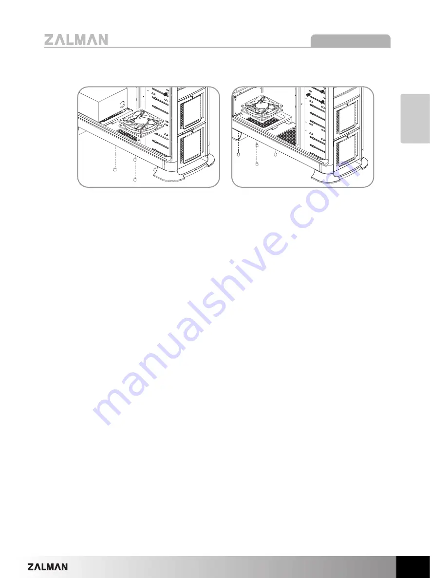
2) Optional Bottom Panel 120mm Fan Installation
Bottom Panel Center Fan Installation
Bottom Panel Rear Fan Installation
Страница 1: ...zalman com English version Please read this manual thoroughly before installation Please visit the GS1000 web page at Zalman s website to view the GS1000 installation video E mail zalman zalman com GS...
Страница 2: ...GS1000 2 1 Cautionary Notes 3 2 Specifications 4 3 Parts List 5 4 Installation 8 5 Options 15 6 Quality Assurance and Warranty Information 16 Contents...
Страница 3: ...ith good ventilation and avoid areas with direct sunlight oil water or excessive moisture 7 Do not cleanse any surface with chemical cleaners or solvents chemicals including but not limited to industr...
Страница 4: ...rd ATX ATX12V PCI AGP card Compatibility Full Size 5 25 Bays x 4 2 can serve as 3 5 3 5 Bays x 6 3 support Hot Swap 3 are optional Cooling Components Top Vent 120mm Fan Vent x 2 1 Fan included 1 optio...
Страница 5: ...5 English GS1000 1 GS1000 3 Parts List Headphones POWER Mic IEEE 1394 USB 2 0 Front View Rear View Top View Side View...
Страница 6: ...1000 Blow Up Diagram Part No Part Name Qty HDD Cover 2 HDD Tray 6 2 in 1 Bracket 2 5 25 Bay Cover 2 Chassis 1 Top Cover 1 Part No Part Name Qty Side Panel 2 PSU Bracket 1 PSU Fan Bracket 1 Rear Foot 1...
Страница 7: ...ension Cable M B Stand Off HDD Screws PSU Screws Foot Fixing Screws FDD Cover CPU Power Extension Cable microATX M B Installation silver HDD Installation black PSU Motherboard Installation black Feet...
Страница 8: ...GS1000 8 1 Feet Assembly 2 Side Panel Removal 4 Installation Front Foot Rear Foot Foot Fixing Screw 1 2...
Страница 9: ...B Type A Type B Type A Type A Type Please position the PSU s intake facing downwards to optimize PSU cooling B Type Please position the PSU s intake facing upwards to optimize system cooling If the sy...
Страница 10: ...5 Hot Swap HDD Installation 1 3 5 HDD Removal Press the corners of the Hot Swap Tray towards the center and pull out as shown in the diagram 1 3 2 M B Stand Off PSU Screw When installing a micro ATX o...
Страница 11: ...Diagram of open HDD Tray 2 3 4 5 6 3 5 HDD 3 5 HDD 3 5 HDD Please secure the HDDs with bolts as shown in the diagram when transporting the case with HDDs installed Be sure to install the HDD s right...
Страница 12: ...GS1000 12 6 5 25 Drive Installation 1 ODD Installation 1 2 3 4 1 2 4 5 3 1 2 3 2 FDD Installation 3 HDD Installation additional HDD installation in a 5 25 bay...
Страница 13: ...omputer OFF prior to installing removing HDDs is recommended Excessive installation removal of HDDs may cause abrasion on component connectors The case comes standard with one Hot Swap PCB 1 Connect t...
Страница 14: ...damage to the system The Power LED will not function properly if connected with the wrong polarity Please check the motherboard s manual before connecting For USB 2 0 IEEE1394a and audio components p...
Страница 15: ...15 English GS1000 2 Optional Bottom Panel 120mm Fan Installation Bottom Panel Center Fan Installation Bottom Panel Rear Fan Installation...
Страница 16: ...16 MEMO...