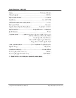


19 Operation and Maintenance Manual
MQ-150 Ballscrew Feed Unit
Disassembly
If your unit is still under the factory warranty period you must contact
Zagar Incorporated Service Department to obtain express written
permission for any repair or service operations. Disassembly of the unit
may result in voiding of the Warranty.
Please note that all socket head cap screw fasteners in the MQ-150 unit are metric.
Proper tooling should be used accordingly. Assembly and disassembly work
should only be done in a clean, assembly area free from chips and contamination.
Removing Spindle
1.
Unthread black front external nut #749-921 using pin type spanner wrench
while pulling spindle nose #749-927 out at the same time. This will remove
the entire spindle assembly.
2.
If spindle assembly needs to be disassembled further for bearing or seal
replacement or change of nose style, remove internal nut #749-922 and
continue unthreading it until it breaks the taper fit of the front spindle nose
#749-927 with the rear spindle body #749-926. Next remove the retaining
ring #11-5100-66 inside of the internal nut and remove the internal nut.
Unthread the lock nut #10-727-4 and the spindle bearings #10-0201-2043-3
can now be pulled off with proper pulling equipment.
Removing spline drive shaft
1.
Remove (4) screws holding outside half of belt guard #749-924 and remove
guard.
2.
Remove all pulleys and belt inside belt guard.
3.
Remove (3) screws holding end cap #749-912 onto feed housing cover #749-
904 and pull entire spline shaft #749-911-1 and end cap assembly out of unit.
4.
To remove spline shaft bearings #10-0171-0036-3, loosen lock nut #10-727-3
and remove lock nut and bearings.
Removing Motors (may vary depending of motor mounting configuration)
1.
Remove feed motor by loosening bolts on feed motor adapter plate #749-907.
Plate will now be free from unit. Carefully pull out to remove pulley from
belt.
2.
If necessary, remove motor from adapter plate by first removing pulley from
motor shaft and then removing (4) screws from motor flange.
3.
To remove spindle motor, remove (4) bolts holding motor onto spindle motor
mount #749-908. Motor will now be free.
Removing quill and ball screw assembly
1.
Remove (4) screws holding inside half of belt guard #749-925 then remove
guard.
2.
Remove (6) socket head cap screws from feed housing cover #749-904 and
remove cover.


