background image

9

CONFIGURATIONS

Doc# 27-0044UM Rev B Issued 7/13/2012

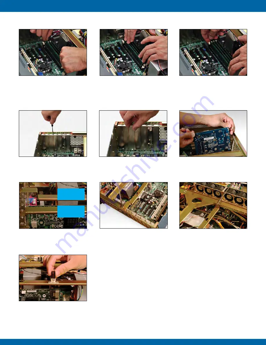
3.4 ChANGING OR RE-INSTALLING A PCI CARd

4. Install the new Memory DIMM by 
carefully aligning the Memory DIMM 
parallel to the slot and then gently but 
firmly inserting. 

5. Carefully push the Memory DIMM in 
using your thumbs.

6. Secure the Memory DIMM by pulling 
the locking latches towards the Memory 
DIMM.

3.3 REMOvING/INSTALLING MEMORY dIMM 

1. Using a Philips screwdriver, remove 
the attachment screw for the selected 
placeholder plate.  

7. Adjust height of the support mechanism. 
Support mechanism slides up and down, 
Make sure of proper engagement to PCI 
card and tighten with a screw-driver.

3. Carefully insert and seat the new 
PCI card into the slot. Once the card is 
secure, select the appropriate Hold Down 
Support Bracket (see next step). 

5. Using a Philips screwdriver, fasten 
the Hold Down Support Bracket  to the 
unit casing.  

2. Remove the plate from the unit casing.

4. For full height cards, use Hold Down 
Support Bracket that is straight across. 
For shorter height cards, use bracket 
with the step down bar (see above).

6. Fasten the opposite side of the Hold 
Down Support Bracket to the unit’s interior 
spanner bracket as shown above.

Full 

Height Cards

Shorter  

Height Cards


Содержание ZX3

Страница 1: ...Microsystems Inc 9820 Summers Ridge Road San Diego CA 92121 T 858 831 7000 F 858 831 7001 www zmicro com ZX3 ZX Series Server Rugged Rack Mounted Workstations Servers for deployed applications User Manual ...

Страница 2: ...of this equipment in a residential area is likely to cause interference in which case the user will be required to correct the interference at his own expense Changes or modifications not expressly approved by Z Microsystems could void user s authority to operate the equipment TO PREVENT FIRE OR SHOCK HAZARDS DO NOT EXPOSE THIS UNIT TO RAIN OR MOISTURE ALSO DO NOT USE THIS UNIT S POLARIZED AC PLUG...

Страница 3: ...pply Module 13 3 6 Installing a New Power Supply Module 13 3 7 Removing the Lockable Face Plate Cover 14 3 8 Installing ther Lockable Face Plate Cover 14 4 0 Operations 14 4 1 Powering on the ZX3 Station 14 4 2 ZX3 Status Information Indicators 14 4 3 Removing the TranzPak2 Storage Module 15 4 4 Inserting a TranzPak2 Storage Module 15 5 0 Maintenance 16 5 1 5 2 Cleaning and Maintaining the ZX3 16 ...

Страница 4: ...d added ease in the installation and operation of the ZX3 Server 1 0 Product overview DANGER To avoid shock hazard Do not remove the covers around the ZX3 Server Do not connect or disconnect the ZX3 Server during an electrical storm The power cord plug must be connected to a properly wired and grounded power outlet Any equipment to which the ZX3 Server will be attached must also be connected to pr...

Страница 5: ...gable TP2 removable drives a slimline DVD RW and an environmental control board to support proper thermal regulation User friendly features include a front accessible power switch two front accessible USB ports for rapid connectivity and a quick release top access cover for ease of service and hardware installation Optimized for rugged conditions the ZX3 Station hosts innovative PCI card hold down...

Страница 6: ...als It may be necessary to move the unit at a later date This section will provide information and assistance with the following topics ZX3 Shipping Contents ZX3 Cable Connections Outline Power Supply Options Using assembly hardware that does not match specifications may damage internal components WARNING For rail installation instructions please refer to the Installation Guide that is included wi...

Страница 7: ...urations are available for Z Microsystem s ZX3 Server Stations A typical dual redundant removeable AC power supply jack is pictured in the full ZX3 configuration above If needed a single fixed DC power supply may be purchased Contact your Z Microsystems Sales Representative for further questions order information and the latest updates and technology DC Power Configuration Schematic outlines for A...

Страница 8: ...Y dimm 1 Loosen both lock screws at the rear of the unit 4 Pull the top back to clear the side tongues from the grooves in the casing and lift the top away 2 Using one hand push slightly down on the front edge of the top and use the other hand to pull the top from the rear or the unit 3 When the top is disengaged from the locked position use your thumbs to apply leverage while your fingers start t...

Страница 9: ...he support mechanism Support mechanism slides up and down Make sure of proper engagement to PCI card and tighten with a screw driver 3 Carefully insert and seat the new PCI card into the slot Once the card is secure select the appropriate Hold Down Support Bracket see next step 5 Using a Philips screwdriver fasten the Hold Down Support Bracket to the unit casing 2 Remove the plate from the unit ca...

Страница 10: ...on casing turn the attachment screws at the rear of the top cover to secure 2 Using one hand push slightly down on the front edge of the top 1 If there is a red light on the front panel then a fan needs to be replaced 7 Lift and remove fan unit from fan assembly 3 Lift and remove the air flow baffle 5 Lift and remove the rear fan cover 2 Using a Philips screwdriver Remove the three screws from the...

Страница 11: ...mple of dual redundant power supplies with IEC connectors 1 Using your fingers twist to remove both screws from the rear top plate of the Power Supply module 2 Insert a finger into the handle and begin to pull the module from the station 3 Gently but firmly continue to pull the Power Supply module out of the ZX3 station 1 Carefully position the Power Supply module to the docking bay 3 Push the uni...

Страница 12: ...de of the face plate cover 1 The face plate cover has small flanges on the left side that perfectly fit within corresponding slots on the support bracket on the left side 4 Align the flanges on the left side of the face plate cover with their corresponding slots on the left support bracket 5 When the left flanges are secured in the support bracket position the right side of the face flat cover ont...

Страница 13: ...ndition User intervention is needed LAN LED 1 and 2 1 Blinking green LAN port is connected and functioning normally 2 OFF LAN port is not connected and or disabled HD LEDs 1 OFF No hard drive activity or no hard drive connected 2 Blinking amber Indicates hard drive activity HEATER LED 1 RESERVED Only in use for systems with optional heater Fan LED LED with Fan text and fan symbol 1 Green system fa...

Страница 14: ...k2 from the rear connector 4 Gently but firmly begin to pull the TranzPak2 module out as it slides off the grounding contacts 2 The locking handle will swing out 1 Raise the TranzPak2 module to the slot and insert into the docking bay 2 Use your thumb to gently push on the TranzPak2 thumb plate in order to slide the module into the docking bay 3 Gently push on the TranzPak2 thumb plate until the m...

Страница 15: ... from the power outlet before cleaning To clean the surface of the ZX3 lightly dampen a soft clean cloth with water or mild detergent and wipe the surface gently 5 2 Replacing the ZX3 air filter This section will provide information and assistance with the following topics Cleaning the ZX3 Server Replacing the ZX3 Air Filter 1 Remove the ZX3 station face plate by twisting the screws on the left si...

Страница 16: ...heck that the power source e g socket extension cord or other source is live and receiving power itself 5 If none of the above resolve the problem contact Z Microsystems Customer Service Department System Beeps Note the number of beeps and or its sequence The motherboard s user manual should contain a reference list for beep patterns and respective indica tions If no motherboard documentation is a...

Страница 17: ...uch of the following informationa s possible 1 Model and serial number for the label on the monitor 2 Purchase P O 3 Description of the problem 4 Computer type and model 5 System configuration hardware fitted etc 6 System BIOS version number 7 Operating System and version number 8 Display driver version number 9 Video Adapter Type Customer Feedback We value feedback on our products their performan...

Страница 18: ...iod from the date the product is shipped This means that the ship date on y our invoice is your product ship date unless Z Microsystems informs you otherwise During the warranty period Z Microsystems will provide warranty service under the type of warranty purchased for the product Replacement parts will assume the remaining warranty of the parts they replace If a product does not function as warr...

Страница 19: ...imately 35 lbs Storage Option SATA or SAS Environmental Operating Temp 0 to 50 Celsius Non Op Temp 40 to 70 Celsius Op Humidity Up to 95 relative humidity per MIL STD 801F section 507 4 optional conformal coated boards required Up to 95 relative humidity per MIL STD 810F section 507 4 for 48 hours with non conformal coated boards Operating Altitude Up to 10 000 ft Non Op Altitude Up to 40 000 ft V...

Страница 20: ...E DECIMALS XX XXX FRACTIONS 1 32 DO NOT SCALE DRAWING MATERIAL A D 05 28 10 SRVR ZX3 ZX3 Phone 858 831 7000 Fax 858 831 7001 9830 Summers Ridge Rd San Diego CA 92121 Z Microsystems Inc S OTHERWISE SPECIFIED E WEIGHT WITHOUT HARD DRIVES 33 LBS DRAWN THIS DOCUMENT IS THE PROPERTY OF Z MICROSYSTEMS INC AND CONTAINS INFORMATION WHICH IS PROPRIETARY TO Z MICROSYSTEMS INC NO PART OF THIS DOCUMENT MAY BE...

Страница 21: ...on Rear view AC DC Power supply Dual Redundant AC PoweR REAR VIEW 20 00 0 75 8 75 17 00 MOUNTING HOLES SLIDE RAILS NOT INSTALLED UNLESS OTHERWIS DIMENSIONS ARE TOLERANCES DECIMALS XX XXX FRACTIONS 1 32 DO NOT SCALE D MATERIAL FINISH N A N A 01 005 APPENDIX ...

Страница 22: ...ad San Diego CA 92121 T 858 831 7000 F 858 831 7001 www zmicro com Z Microsystems Inc 9820 Summers Ridge Road San Diego CA 92121 Phone 858 831 7000 Fax 858 831 7001 Website www zmicro com Copyright 2012 Z Microsystems Inc All Rights Reserved ...

Отзывы: