DISTRIBUTION ZHC
User Manual and Installation Guide
10
1.
The Hub is designed to be rack mounted in a standard EIA 19” rack. Rack all Fiber units in the
install but DO NOT POWER units up at this time.
Use a quality 75Ω RG6 or RG11 coaxial cable
with “F” connectors to cable the coax cascade backbone to all units (Reference Following
Cascade
section). Recommended that you use Z-Band design drawing.
2.
Rack the Fiber TX at the headend, as well as the Fiber coupler (if needed).
It is
recommended that a Z-Band Light Fiber TX be used, as this unit will automatically
correct for channel loading. If not using a Z-Band Light unit, please refer to the
Fiber T
X manufacturer’s guide for proper channel load/level set-up.
3.
At RF headend adjust signal so that the input to the Z-Band Light Fiber TX is 20+/-2 dBmV for
all channels across the spectrum for digital, or is 23 dBmV+/-2 for analog. It is extremely
important that the whole spectrum is FLAT (0 slope) for the system to preform properly. Also
ensure that the signal quality is good. That means for all digital signals a MER of >36dB and
for analog a CN of >46 dB. If your quality is below that going into the system, the resulting feed
may encounter problems. If your feed is bad, please contact your Cable Service Provider to
correct.
These measurements should be taken at the end of the cable that is to attach to
the Master ZHC
.
4.
Connect the fiber patch from the Fiber TX to the Fiber Coupler (if used), and then from the Fiber
Coupler to the fiber patch tray.
5.
In the closet where the ZHC Fiber Hub resides, attach the fiber patch cord to the fiber patch
tray. Measure the output from the fiber patch to verify that it is within the required limit of -1 to -
5 dBm.
6.
Attach the fiber patch to the SC/APC fiber connector on the rear of the ZHC Hub.
M
S
P
1
2
3
4
5
6
7
8
9
10
11
12
13
14
15
16
17
18
19
20
21
22
23
24
CATV/CAS
IN
OUTBOUND COAX
LC/ APC
FIBER
MGMT
Z- Distribution
ZHC
A
B
12 VDC
USB
M
S
P
1
2
3
4
5
6
7
8
9
10
11
12
13
14
15
16
RF IN
OUTBOUND COAX
MGMT
Z- Distribution
ZHC
A
B
12VDC
USB
MASTER
1
ST
LEVEL SLAVE
FIBER
INPUT
CASCADE
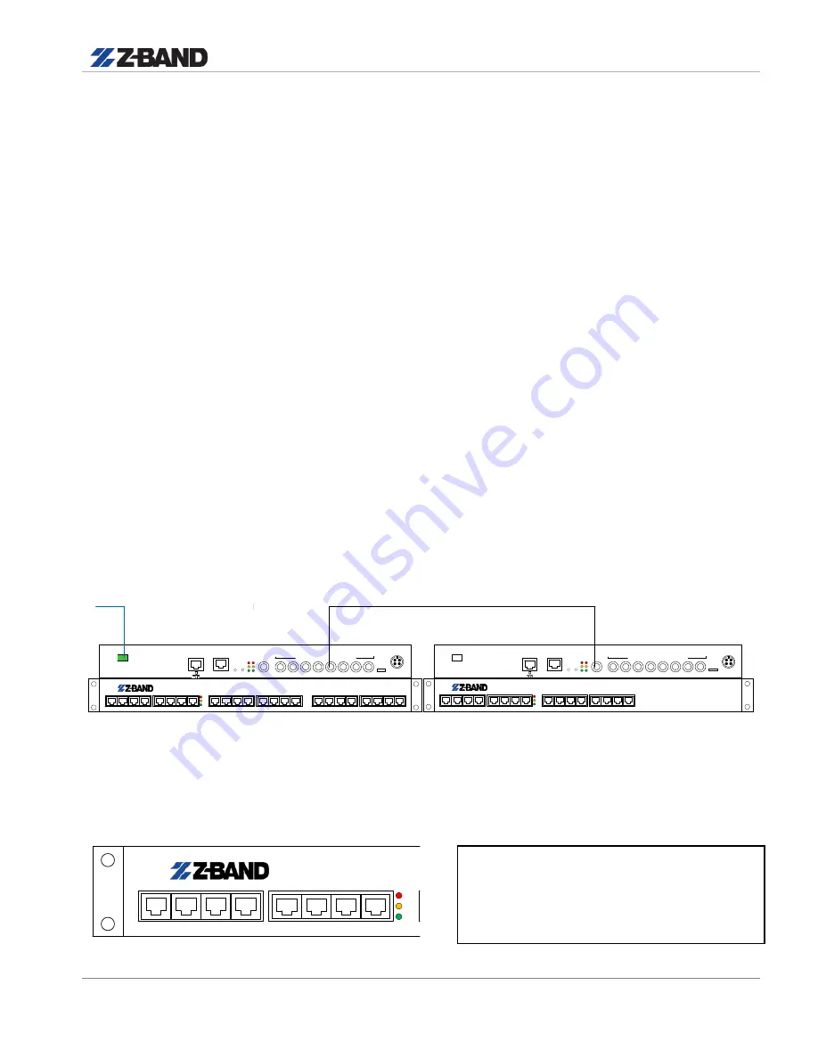
7.
Power up Master unit only. Note the 3 LED’s of the left side of the front panel. Upon powering
unit, all 3 LED’s will be lit. After ~30 seconds, the middle Yellow LED will go out. This
indicates that the unit had adjusted to Master
M
S
P
1
2
3
4
5
6
7
8
9
10
11
12
13
14
15
16
17
18
19
20
21
22
23
24
CATV/CAS
IN
OUTBOUND COAX
LC/APC
FIBER
MGMT
Z-Distribution
ZHC
A
B
12VDC
USB
FRONT PANEL
•
When Powered on all 3 LED’s lit
•
After ~30 sec’s Yellow goes out
•
Only Red and Green are lit. Unit
now Auto Adjusted in Fiber Master


