Yumpu 000K-B-10 Скачать руководство пользователя страница 4

4

Before You Install this Appliance

 This equipment is securely packaged at the time of 

shipment and upon arrival should be carefully inspected 
for damage prior to installing the equipment at the job 
site. Claims for damage (apparent or concealed) should 
be filed immediately with the carrier.

 The heating load of the area must be calculated 

and a system of the proper capacity selected. It is 
recommended that the area to be heated be completely 
insulated and vapor sealed.

  Check the electrical supply and verify the power supply 

is adequate for unit operation. The system must be wired 
and provided with circuit protection in accordance with 
local building codes. If there is any question concerning 
the power supply, contact the local power company.

  Verify the static pressure drop of the coil, filter, and duct 

work do not exceed the air delivery specs of the electric 
furnace.

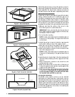
Locating the Electric furnace

•  Survey the job site to determine the best location for 

mounting the unit. Consideration should be given to 
availability of electric power, service access, and noise.

•  The dimensions of the room or alcove must be able 

to accommodate the overall size of the unit and the 
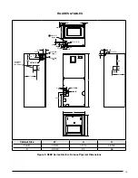
installation clearances listed in Figure 1. Physical 
dimensions for this electric furnace are also shown in 
Figure 9 (page 13).

•  The electric furnace should be installed before routing 

the refrigerant tubing.

•  This  unit  should  be  located  with  consideration  of 

minimizing the length of the supply and return ducts. 
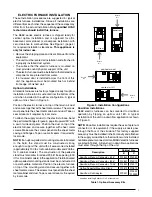
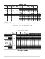
Refer to the rating plate or Table 3 (page 15) for proper 
circulating airflow data.

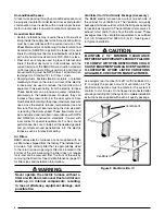
Figure 1. Minimum Unit Clearances

INSTALLATION CLEARANCES

Left Side ......... 0 Inches Right Side ...... 0 Inches
Back ............... 0 Inches Front ...........

See Notes

NOTES:

Closet or Alcove Installations:

•  Allow 24 in. minimum clearance from front of unit to 

nearest wall or partition for servicing. Recommended 
clearance is 36 in.

•  A return air grill should be installed in the door or a 

partially louvered door across the opening for proper 
air circulation. Provide at least 235 in

2

 free opening 

for return air for B-cabinet models and 300 in

2

 for 

C-cabinet models. A fully louvered closet door is 
strongly recommended for both installation types

REAR

RIGHT

SIDE

LEFT
SIDE

FRONT

Minimum Clearances

•  This  appliance  must  be  installed  in  accordance  with 

clearances listed in Figure 1. The electric furnace must 
be installed with ample clearance for easy access to the 
air filter, blower assembly, heater assembly, controls, 
and vent connections.

•  Sufficient clearance for unobstructed airflow through a 

louvered door must be maintained in order to achieve 
rated performance.

•  All electric heater kits less than 20 kw  are approved for 

use in electric furnace installations with zero-clearance 
to combustibles at any blower speed. For horizontal and 
upflow configuration, B5 electric furnaces equipped with 
20 kw electric heater kits are approved for installation 
with zero clearance to combustibles at any blower speed.

Содержание 000K-B-10

Страница 1: ...cial notes highlighted in the manual Improper installation of the furnace or failure to follow safety warnings could result in serious injury death or property damage Please read all instructions care...

Страница 2: ...Supply Circuits 10 Control Board 10 Twinning 10 Thermostat Low Voltage Connections 10 Grounding 10 Startup Adjustments 11 Before You Start the Unit 11 Air Circulation Check 11 Running the Blower Conti...

Страница 3: ...ctric Code ANSI NFPA 70 For Canadian installations the electrical connectionsandgroundingshallcomplywiththecurrent Canadian Electrical Code CSA C22 1 and or local codes Installationofequipmentmayrequi...

Страница 4: ...rant tubing This unit should be located with consideration of minimizing the length of the supply and return ducts Refer to the rating plate or Table 3 page 15 for proper circulating airflow data Figu...

Страница 5: ...essure shown on the furnace rating plate The supply air must be delivered to the heated space by duct s secured to the furnace casing running full length and without interruption Circulating Air Suppl...

Страница 6: ...r best sound performance be sure to install all the needed gaskets and grommets around penetrations into the electric furnace such as for electrical wiring Air Filters B5BV series electric furnaces ar...

Страница 7: ...th sheet metal screws Make sure the screws penetrate the sheet metal casing and flanges Tape or seal all seams if required by local code NOTE If an upflow pedestal mounting stand is fabricated in the...

Страница 8: ...nnector and cut out the marked area of the supply air duct NOTE Toallowsomeclearanceforinstallingtheplenum connector cut the opening 1 4 larger the actual cutout drawn 6 Install the duct connector bac...

Страница 9: ...lso be installed in a horizontal application with the unit suspended from the ceiling If suspending the electricfurnacefromtheceiling assembleasupportframe using slotted iron channel and full threaded...

Страница 10: ...ce controls the timing sequence of the elements The board is equipped with a 3 second blower ON delay and a 15 second blower OFF delay in heating and a 40 second blower OFF delay in cooling Twinning E...

Страница 11: ...temperature above room temperature and observe that the blower energizes Checktheairbeingdischargedattheregister is warmer than room temperature 2 Allow the unit to run for several minutes and then se...

Страница 12: ...s recommended that the filter be cleaned or replacedmonthly Newlybuiltorrecentlyrenovatedhomes mayrequiremorefrequentchanginguntiltheconstruction dust has minimized Filter sizes shown in Table 2 are a...

Страница 13: ...B 19 3 4 18 1 4 49 3 8 C 22 1 2 21 56 3 4 3 4 3 4 13 1 7 8 K O 11 8 K O typ 11 4 15 8 17 8 11 4 3 1 4 2 5 8 11 8 K O typ 13 4 K O typ 1 7 8 3 5 8 5 5 8 DETAIL D 3 1 4 2 1 4 15 1 4 13 SUCTION LIQUID W...

Страница 14: ...Transformer Capacitor Circuit Breaker 60A Heating Element Assembly Blower Wheel Blower Housing Motor Control Board Control Board Filter Door Upper Door Assembly Lower Door Assembly Figure 10 B5BV Ser...

Страница 15: ...1576 1783 NOTES 1 Airflow is shown in cfm 5 2 All airflows are measured without filter and with dry coil For filter velocity of 300 ft min subtract 08 external static pressure For wet coil subtract 1...

Страница 16: ...peed tap connection may not be as shown See the Installation Instructions 2 Disconnect all power before servicing 3 Transformer may have a dual voltage primary tap Match the tap position with the supp...

Страница 17: ...GREY BLUE ORANGE POWER PLUG LIMIT RED RED RED RED BLACK BLACK RED BLACK RELAY RELAY TERMINAL BLOCK for select models only CIRCUIT BREAKER Circuit breaker models only BLUE W2 W1 O Y Y2 G R C X13 MOTOR...

Страница 18: ...d 4 If the Internal wiring is replaced use only 105 C copper wire of the same gauge W2 W1 O Y Y2 G R C 4 SPD MOTOR 1 2 3 5 6 4 TRANSFORMER 24V BLACK RED WHITE BLACK WHITE FUSE L2 COM 2 L2 L2 COM L1 VS...

Страница 19: ...ANSFORMER 24V BLACK RED WHITE BLACK WHITE FUSE BLOWER MOTOR PLUG C L G N N NEUTRAL G GROUND L LINE C COMMON L2 L2 L2 COM L1 L1 XFMR X13 COOL X13 HEAT 24 VAC RED COM GREY Y1 C L G N WHITE X13 COM RED B...

Страница 20: ...h B5 Electric Furnace G R C E O Y Thermostat NOTE Jumper W1 W2 together for shorter staging time W2 W1 O Y G R C W2 W1 O Y G R C NOTE Jumper W1 W2 together for shorter staging time Air Handler W2 O W2...

Страница 21: ...21...

Страница 22: ...22...

Страница 23: ...23...

Страница 24: ...at been calibrated YES NO Is the thermostat level YES NO Is the heat anticipator setting correct YES NO VENTING SYSTEM Is there adequate fresh air supply for ventilation YES NO Vent free from restrict...

Отзывы: