Yumpu 000K-B-10 Скачать руководство пользователя страница 3

3

IMPORTANT SAFETY INFORMATION

NOTE TO INSTALLER: Please read all instructions 
before servicing this equipment. Pay attention to all safety 
warnings and any other special notes highlighted in the 
manual.

Safety markings are used frequently throughout this 
manual to designate a degree or level of seriousness and 
should not be ignored. 

WARNING

 indicates a potentially 

hazardous situation that if not avoided, could result in 
personal injury or death. 

CAUTION

 indicates a potentially 

hazardous situation that if not avoided, may result in minor 
or moderate injury or property damage.

 WARNING:

ELECTRICAL ShOCK, FIRE OR EXPLOSION 
hAZARD

Failure to follow safety warnings exactly could 
result in serious injury or property damage.
Improper servicing could result in dangerous 
operation, serious injury, death or property 
damage.

•  Before servicing, disconnect all electrical power 

to electric furnace.

•  When servicing controls, label all wires prior 

to disconnecting. Reconnect wires correctly.

•  Verify proper operation after servicing.

GENERAL INFORMATION

Requirements & Codes

 WARNING:

This unit must be installed in accordance with 
instructions outlined in this manual during 
the installation, service, and operation of 
this unit. Unqualified individuals should not 
attempt to interpret these instructions or 
install this equipment. Failure to follow safety 
recommendations could result in possible 
damage to the equipment, serious personal 
injury or death.

•  The  installer  must  comply  with  all  local  codes  and 

regulations which govern the installation of this type 
of equipment. Local codes and regulations take 
precedence over any recommendations contained in 
these instructions. Consult local building codes for 
special installation requirements.

•  This equipment contains nitrogen gas. Installation or 

servicing should only be performed by qualified trained 
personnel thoroughly familiar with this type equipment.

• 

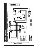
Electrical power wiring must be made in accordance 
with all applicable local codes and ordinances, and with 
the current revision of the National Electric Code (ANSI/
NFPA 70). For Canadian installations, the electrical 
connections and grounding shall comply with the current 
Canadian Electrical Code (CSA C22.1 and/or local 
codes).

•  Installation of equipment may require brazing operations. 

Installer must comply with safety codes and wear 
appropriate safety equipment (safety glasses, work 
gloves, fire extinguisher, etc.) when performing brazing 
operations.

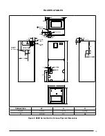
•  Install  this  unit  only  in  a  location  and  position  as 

specified on page 4. This unit is designed only for Indoor 
installations and should be located with consideration 
of minimizing the length of the supply and return ducts. 
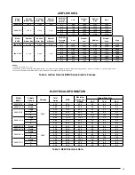
Refer to the rating plate or Table 3 (page 15) for proper 
airflow data.

•  Follow  all  precautions  in  the  literature,  on  tags,  and 

on labels provided with the equipment. Read and 
thoroughly understand the instructions provided with 
the equipment prior to performing the installation and 
operational checkout of the equipment.

About the Electric furnace

This appliance has been tested and certified by AHRI for 
capacity and efficiency and will provide many years of safe 
and dependable comfort, providing it is properly installed 
and maintained. Abuse, improper use, and/or improper 
maintenance can shorten the life of the appliance and 
create unsafe hazards. Please read all instructions before 
installing the unit.

The B5BV Series electric furnace is approved for use 
in HUD code manufactured homes (HUD Manufactured 
Home Construction and Safety Standard (Title 24, Part 
3280) and other modular home applications.

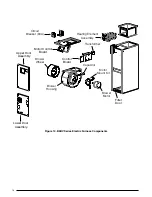
B5BV Series electric furnaces are supplied with factory 
installed electric heat. Only approved heat-pump/air 
conditioning coils may be installed in the field. Unless 
otherwise noted in the instructions, only factory authorized 
kits or accessories may be used when modifying this 
product.

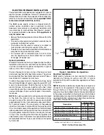
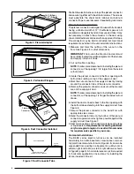
Mounting Applications

Vertical only electric furnaces are factory ready for upflow 
applications. These units may be applied in downflow 
or horizontal left and right discharge applications when 
applied with the appropriate field kit.

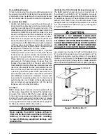
Through-the-floor installations require a 1/4” thick 
noncombustible resilient gasket to be used whenever the 
supply or return air ducts pass through the floor. The gasket 
should be positioned between the duct, unit, and floor.

Содержание 000K-B-10

Страница 1: ...cial notes highlighted in the manual Improper installation of the furnace or failure to follow safety warnings could result in serious injury death or property damage Please read all instructions care...

Страница 2: ...Supply Circuits 10 Control Board 10 Twinning 10 Thermostat Low Voltage Connections 10 Grounding 10 Startup Adjustments 11 Before You Start the Unit 11 Air Circulation Check 11 Running the Blower Conti...

Страница 3: ...ctric Code ANSI NFPA 70 For Canadian installations the electrical connectionsandgroundingshallcomplywiththecurrent Canadian Electrical Code CSA C22 1 and or local codes Installationofequipmentmayrequi...

Страница 4: ...rant tubing This unit should be located with consideration of minimizing the length of the supply and return ducts Refer to the rating plate or Table 3 page 15 for proper circulating airflow data Figu...

Страница 5: ...essure shown on the furnace rating plate The supply air must be delivered to the heated space by duct s secured to the furnace casing running full length and without interruption Circulating Air Suppl...

Страница 6: ...r best sound performance be sure to install all the needed gaskets and grommets around penetrations into the electric furnace such as for electrical wiring Air Filters B5BV series electric furnaces ar...

Страница 7: ...th sheet metal screws Make sure the screws penetrate the sheet metal casing and flanges Tape or seal all seams if required by local code NOTE If an upflow pedestal mounting stand is fabricated in the...

Страница 8: ...nnector and cut out the marked area of the supply air duct NOTE Toallowsomeclearanceforinstallingtheplenum connector cut the opening 1 4 larger the actual cutout drawn 6 Install the duct connector bac...

Страница 9: ...lso be installed in a horizontal application with the unit suspended from the ceiling If suspending the electricfurnacefromtheceiling assembleasupportframe using slotted iron channel and full threaded...

Страница 10: ...ce controls the timing sequence of the elements The board is equipped with a 3 second blower ON delay and a 15 second blower OFF delay in heating and a 40 second blower OFF delay in cooling Twinning E...

Страница 11: ...temperature above room temperature and observe that the blower energizes Checktheairbeingdischargedattheregister is warmer than room temperature 2 Allow the unit to run for several minutes and then se...

Страница 12: ...s recommended that the filter be cleaned or replacedmonthly Newlybuiltorrecentlyrenovatedhomes mayrequiremorefrequentchanginguntiltheconstruction dust has minimized Filter sizes shown in Table 2 are a...

Страница 13: ...B 19 3 4 18 1 4 49 3 8 C 22 1 2 21 56 3 4 3 4 3 4 13 1 7 8 K O 11 8 K O typ 11 4 15 8 17 8 11 4 3 1 4 2 5 8 11 8 K O typ 13 4 K O typ 1 7 8 3 5 8 5 5 8 DETAIL D 3 1 4 2 1 4 15 1 4 13 SUCTION LIQUID W...

Страница 14: ...Transformer Capacitor Circuit Breaker 60A Heating Element Assembly Blower Wheel Blower Housing Motor Control Board Control Board Filter Door Upper Door Assembly Lower Door Assembly Figure 10 B5BV Ser...

Страница 15: ...1576 1783 NOTES 1 Airflow is shown in cfm 5 2 All airflows are measured without filter and with dry coil For filter velocity of 300 ft min subtract 08 external static pressure For wet coil subtract 1...

Страница 16: ...peed tap connection may not be as shown See the Installation Instructions 2 Disconnect all power before servicing 3 Transformer may have a dual voltage primary tap Match the tap position with the supp...

Страница 17: ...GREY BLUE ORANGE POWER PLUG LIMIT RED RED RED RED BLACK BLACK RED BLACK RELAY RELAY TERMINAL BLOCK for select models only CIRCUIT BREAKER Circuit breaker models only BLUE W2 W1 O Y Y2 G R C X13 MOTOR...

Страница 18: ...d 4 If the Internal wiring is replaced use only 105 C copper wire of the same gauge W2 W1 O Y Y2 G R C 4 SPD MOTOR 1 2 3 5 6 4 TRANSFORMER 24V BLACK RED WHITE BLACK WHITE FUSE L2 COM 2 L2 L2 COM L1 VS...

Страница 19: ...ANSFORMER 24V BLACK RED WHITE BLACK WHITE FUSE BLOWER MOTOR PLUG C L G N N NEUTRAL G GROUND L LINE C COMMON L2 L2 L2 COM L1 L1 XFMR X13 COOL X13 HEAT 24 VAC RED COM GREY Y1 C L G N WHITE X13 COM RED B...

Страница 20: ...h B5 Electric Furnace G R C E O Y Thermostat NOTE Jumper W1 W2 together for shorter staging time W2 W1 O Y G R C W2 W1 O Y G R C NOTE Jumper W1 W2 together for shorter staging time Air Handler W2 O W2...

Страница 21: ...21...

Страница 22: ...22...

Страница 23: ...23...

Страница 24: ...at been calibrated YES NO Is the thermostat level YES NO Is the heat anticipator setting correct YES NO VENTING SYSTEM Is there adequate fresh air supply for ventilation YES NO Vent free from restrict...

Отзывы: