


14
YT-3300/3301 series
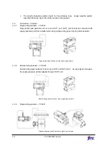
3. Attach the positioner with bracket to the actuator yoke –
DO NOT TIGHTEN
POSITIONER COMPLETELY.
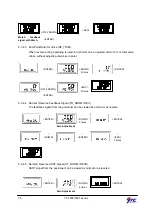
4. Connect positioner’s feedback lever to the actuator clamp. The hole gap on the
feedback lever is 6.5mm. The connection pin’s outer diameter should be less than
6.3mm.
5. Connect supply pressure to the actuator temporarily. Supply enough supply pressure to
the actuator in order to position the actuator clamp at 50% of the total valve stroke.
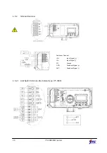
6. Insert connection pin into the feedback lever. The pin should be inserted when the
actuator clamp is at 50% of the total valve stroke.
Proper way to connect feedback lever, connection pin, and lever spring <YT-3300 and YT-3301 sensor>
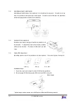
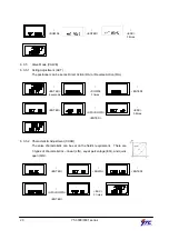
7. Check if feedback lever is parallel to the ground at 50% of the valve stroke. If it is not
parallel, adjust the bracket or feedback link bar to make parallel. Improper installation
may cause poor linearity and may create unnecessary hunting during the operation.
8. Check the valve stroke. The stroke marks are indicated on the feedback lever of the
positioner. Position the connection pin at the number on the feedback lever which
corresponds to the desired valve stroke. To adjust, move the bracket, the connection
pin or both.
Proper way of Pin Insertion
Содержание YT-3300 Series
Страница 1: ...SMART POSITIONER PRODUCT MANUAL YT 3300 3301 SERIES VERSION 1 02...
Страница 4: ...4 YT 3300 3301 series 7 2 Warning Code 33 8 Main Software Map 35...
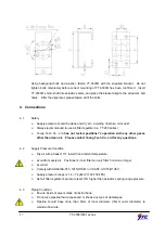
Страница 10: ...10 YT 3300 3301 series 2 7 Parts and Assembly YT 3301L YT 3301R 2 8 Product Dimension 2 8 1 YT 3300L...
Страница 11: ...11 YT 3300 3301 series 2 8 2 YT 3300R 2 8 2 1 YT 3300R standard 2 8 2 2 YT 3300R with L S option...
Страница 12: ...12 YT 3300 3301 series 2 8 3 YT 3301L 2 8 4 YT 3301R...
Страница 35: ...35 YT 3300 3301 series 8 Main Software Map...


