background image

27

JOHNSON CONTROLS

FORM 150.72-NM3 (1020) 

ISSUE DATE 10/05/2020

SECTION 2 – PRODUCT DESCRIPTION

2

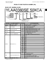
PRODUCT IDENTIFICATION NUMBER (PIN)

BASIC UNIT NOMENCLATURE

YLAA0360SE 50XCA

1 2 3 4

9

12

13

14 15

10

11

A = Development Level

Four Digit Unit Number

Y = YORK

L = Scroll

A = Americas

E = Europe

A = Air Cooled 

Condensing Unit

C = Design Series A, B, C

X = Across the Line

50 = 380/415-3-50

E = R-410A

S = Standard Efficiency

H = High Efficiency

Z = Standard Efficiency (round tube)

Y = High Efficiency (round tube)

BASE PRODUCT TYPE

5 6 7 8

NOMINAL 

CAPACITY

UNIT 

DESIGNATOR

REFRIGERANT VOLTAGES

STARTER DESIGN/DEVELOPMENT 

LEVEL

FEATURE

FEATURE DESCRIPTION

OPTION

OPTION DESCRIPTION

CONTRACT

CONTRACT NUMBER

NUM

CONTRACT NUMBER = {CONTRACT/NUM}

ORDER

ORDER QUANTITY

QTY

ORDER QUANTITY = { ORDER/QTY }

USA

USA ORIGIN

N

USA ORIGIN NOT REQUIRED

Y

USA ORIGIN REQUIRED

SHIPWT

SHIPPING WEIGHT

LBS

CRANE/RIGGING SHIPPING WEIGHT = {LBS}

KG

CRANE/RIGGING SHIPPING WEIGHT = {KG}

STOCK

STOCK UNIT

N

UNIT BEING BUILT FOR SOLD ORDER

Y

UNIT BEING BUILT FOR STOCK

CONV

STOCK CONVERSION

N

NOT A CONVERSION

C

ORDER BEING CONVERTED FROM STOCK

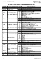
MODEL

MODEL (PIN 1-4)

YLAA

YLAA

0195

0195

0220

0220

0260

0260

0285

0285

0300

0300

0320

0320

0350

0350

0360

0360

0390

0390

0400

0400

0435

0435

0440

0440

0455

0455

0485

0485

0515

0515

UNIT

UNIT DESIGNATOR (PIN 9)

S

STANDARD EFFICIENCY

H

HIGH EFFICIENCY

Y

HIGH EFFICIENCY (ROUND TUBE)

Z

STANDARD EFFICIENCY (ROUND TUBE)

REF

REFRIGERANT (PIN 10)

E

R-410A

Содержание YLAA0285SE

Страница 1: ...ILS STYLE A 50 HZ 57 142 TON Products are produced at a facility whose quality management systems are ISO9001 certified R 410A Issue Date October 5 2020 035 21911 001 AIR COOLED SCROLL CHILLER INSTALL...

Страница 2: ...ials This individual shall also be familiar with and comply with all applicable governmental standards and regulations pertaining to the task in question SAFETY SYMBOLS The following symbols are used...

Страница 3: ...F THIS DOCUMENT REVISION NOTES Revisions made to this document are indicated in the following table These revisions are to technical information and any other changes in spelling grammar or formatting...

Страница 4: ...High Temperature and Pressure Cleaning 15 Emergency Shutdown 15 SECTION 2 PRODUCT DESCRIPTION 17 INTRODUCTION 17 GENERAL SYSTEM DESCRIPTION 17 Compressors 17 Cooler Evaporator 17 Condenser 18 HIGH AM...

Страница 5: ...acts 40 System Run Contacts 40 Alarm Status Contacts 41 Remote Start Stop Contacts 41 Remote Emergency Cutoff 41 Remote Temp Reset Input 41 Load Limit Input 41 Flow Switch Input 41 COMPRESSOR HEATERS...

Страница 6: ...Spring Isolators Installation Instructions 125 Seismic Isolator Cross reference 126 Seismic Isolator Installation and Adjustment INSTRUCTIONS 127 Duralene Isolator Cross reference 128 Installation of...

Страница 7: ...S 145 Oper Data Key 145 Oper Data Quick Reference List 148 Print Key 149 Operating Data Printout 149 History Printout 150 History Displays 150 Software Version 152 ENTRY KEYS 153 Up and Down Arrow Key...

Страница 8: ...OR HEATER CONTROL 171 PUMPDOWN CONTROL 171 STANDARD CONDENSER FAN CONTROL 171 LOAD LIMITING 175 COMPRESSOR RUN STATUS 175 ALARM STATUS 175 BAS EMS TEMPERATURE RESET USINGA VOLTAGE OR CURRENT SIGNAL 17...

Страница 9: ...ARD BATTERY BACK UP 189 PLATE AND FRAME HEAT EXCHANGER EVAPORATOR HEATER 189 OVERALL UNIT INSPECTION 189 MICROCHANNEL COIL CLEANING 190 BACNET MODBUS AND YORKTALK 2 COMMUNICATIONS 191 BACnet and Modbu...

Страница 10: ...IRING DIAGRAM YLAA0195 SHT 9 72 FIG 21 CONNECTION WIRING DIAGRAM YLAA0195 SHT 1 74 FIG 22 CONNECTION WIRING DIAGRAM YLAA0195 SHT 2 76 FIG 23 CONNECTION WIRING DIAGRAM YLAA0195 SHT 3 78 FIG 24 CONNECTI...

Страница 11: ...OLATOR MOUNTING POSITIONS 121 FIG 52 ONE INCH DEFLECTION SPRING ISOLATOR CROSS REFERENCE 124 FIG 53 ONE INCH DEFLECTION SPRING ISOLATORS INSTALLATION INSTRUCTIONS 125 FIG 54 SEISMIC ISOLATOR CROSS REF...

Страница 12: ...URN CHILLED LIQUID CONTROL FOR 4 COMPRESSORS 6 STEPS 170 TABLE 16 RETURN CHILLED LIQUID CONTROL FOR 4 COMPRESSORS 6 STEPS 170 TABLE 17 YLAA STANDARD CONDENSER FAN CONTROL USING DISCHARGE PRESSURE ONLY...

Страница 13: ...iod and that the unit has been operated within the designed parameters specified All warranty claims must specify the unit model serial number order number and run hours starts Model and serial number...

Страница 14: ...manual and any other document supplied with the unit are the property of Johnson Controls which reserves all rights They may not be reproduced in whole or in part without prior written authorization...

Страница 15: ...isk of injury from rotating fans Sharp Edges The fins on the air cooled condenser coils have sharp metal edges Reasonable care should be taken when working in contact with the coils to avoid the risk...

Страница 16: ...JOHNSON CONTROLS 16 FORM 150 72 NM3 1020 ISSUE DATE 10 05 2020 SECTION 1 GENERAL CHILLER INFORMATION and SAFETY THIS PAGE INTENTIONALLY LEFT BLANK...

Страница 17: ...lds a minimum ASTM 1654 rating of 6 Units are designed in accordance with NFPA 70 National Electric Code ASHRAE ANSI 15 Safety code for mechanical refrigeration ASME and rated in accordance with ARI S...

Страница 18: ...otected They feature ball bearings that are double sealed and permanently lubricated Ambient Kit High Required if units are to operate when the ambient temperature is above 46 C 115 F Includes dischar...

Страница 19: ...temperature reset and two steps of demand load limiting from an external building automation system Unit alarm contacts are standard Intensity of Protection European Standard International Electrotech...

Страница 20: ...lock able handle in compliance with N E C Article 440 14 can be supplied to isolate the power voltage for servicing This option includes the Single Point Power connection CONTROL TRANSFORMER Converts...

Страница 21: ...on for upright mounting in horizontal pipe This flow switch or equivalent must be furnished with each unit HYDRO KIT Factory installed Hydro Kit suitable for water glycol systems with up to 35 glycol...

Страница 22: ...d to exposed coil end Factory mounted SOUND ATTENUATION One or both of the following sound attenuation options are recommended for residential or other similar sound sensitive locations COMPRESSOR ACO...

Страница 23: ...TE 10 05 2020 SECTION 2 PRODUCT DESCRIPTION 2 FIG 1 UNIT COMPONENTS FRONT UNIT COMPONENTS LD14317 FAN DECK POWER PANEL CONTROL PANEL COMPRESSORS FORMED BASE RAIL EVAPORATOR TXV VALVES SIGHT GLASS FILT...

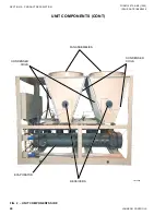
Страница 24: ...CONTROLS 24 FORM 150 72 NM3 1020 ISSUE DATE 10 05 2020 SECTION 2 PRODUCT DESCRIPTION FIG 2 UNIT COMPONENTS SIDE UNIT COMPONENTS CONT FAN ASSEMBLIES CONDENSER COILS CONDENSER COILS EVAPORATOR RECEIVERS...

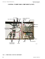
Страница 25: ...3 1020 ISSUE DATE 10 05 2020 SECTION 2 PRODUCT DESCRIPTION 2 LD13247 FIG 3 POWER PANEL COMPONENTS CONTROL POWER PANEL COMPONENTS COMPRESSOR CONTACTORS XTBF1 FAN CONTACTORS FAN CONTACTOR COMPRESSOR OVE...

Страница 26: ...2 PRODUCT DESCRIPTION CONTROL POWER PANEL COMPONENTS CONT FIG 4 POWER PANEL CONTROL COMPONENTS COMPRESSOR OVERLOADS COMPRESSOR CONTACTORS FAN CONTACTORS FAN FUSES CONTROL RELAY MICROCOMPUTER CONTROL...

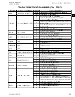
Страница 27: ...DESCRIPTION OPTION OPTION DESCRIPTION CONTRACT CONTRACT NUMBER NUM CONTRACT NUMBER CONTRACT NUM ORDER ORDER QUANTITY QTY ORDER QUANTITY ORDER QTY USA USA ORIGIN N USA ORIGIN NOT REQUIRED Y USA ORIGIN...

Страница 28: ...SPECIAL CONTROL TRANSFORMER REQUIRED PFC POWER FACTOR CAPACITOR 19 X NO POWER CAPACITOR REQUIRED C POWER CAPACITOR REQUIRED Q SPECIAL POWER CAPACITOR REQUIRED AMB AMBIENT KITS PIN 20 H HIGH AMBIENT K...

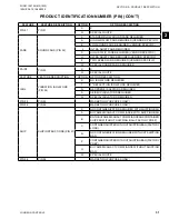
Страница 29: ...ED 1 HOT GAS BYPASS REQUIRED 1 CIRCUIT Q SPECIAL HOT GAS BYPASS REQUIRED GAUGE PIN 34 X X Q SPECIAL QUOTE OVERLOAD PIN 35 X X Q SPECIAL QUOTE PIN36 PIN 36 X X Q SPECIAL QUOTE HTR CRANKCASE HEATER PIN...

Страница 30: ...1 WIRE FULL UNIT ENCL PANELS FACTORY 2 WIRE FULL UNIT ENCL PANELS FIELD 3 WIRE LOUVERED ENCL PANELS FACTORY 4 WIRE LOUVERED ENCL PANELS FIELD 5 LOUVERED COND ONLY ENCL PANELS FACTORY 6 LOUVERED COND O...

Страница 31: ...QUOTE FEATURE FEATURE DESCRIPTION OPTION OPTION DESCRIPTION ISOL VIBRATION ISOLATORS PIN 54 X NO ISOLATORS REQUIRED 1 1 DEFLECTION ISOLATORS REQUIRED N NEOPRENE ISOLATORS REQUIRED S SEISMIC ISOLATORS...

Страница 32: ...REQUIRED K PUMP KIT K REQUIRED L PUMP KIT L REQUIRED M PUMP KIT M REQUIRED N PUMP KIT N REQUIRED O PUMP KIT O REQUIRED P PUMP KIT P REQUIRED R PUMP KIT R REQUIRED Q SPECIAL QUOTE PKGOPT PUMP PACKAGE...

Страница 33: ...AL SERVICE VALVE LOW PRESSURE SWITCH OR SUCTION PRESSURE TRANSDUCER LEAVING CHILLED WATER TEMP SENSOR RETURN WATER TEMP SENSOR OPTIONAL DISCHARGE LINE BALL VALVE HOT DISCHARGE GAS LINE LIQUID LINE SER...

Страница 34: ...Chilled Liquid See P R V Options Compressors Control Functions DV Display Value CHT Chilled Liquid Temperature HPC High Pressure Cutout LPC Low Pressure Cutout HPL High Pressure Load Limiting LTC Low...

Страница 35: ...ng and inspect the unit to ensure that all components have been delivered and that no damage has occurred during transit If any damage is evident it should be noted on the carrier s freight bill and a...

Страница 36: ...ars to avoid lifting chains hitting the chiller Never lift the chiller using a forklift or by hooking to the top rails Use only the lifting holes provided Lifting Instructions are placed on a label on...

Страница 37: ...e occurred during transit If damage is evident it should be noted in the carrier s freight bill A written request for inspection by the carrier s agent should be made at once See Instruction manual Fo...

Страница 38: ...nimize vibration Noise Sensitive Locations Efforts should be made to assure that the chiller is not located next to occupied spaces or noise sensitive areas where chiller noise level would be a proble...

Страница 39: ...ure gauges should be installed in the inlet and outlet water lines 6 The chilled water lines that are exposed to outdoor ambients should be wrapped with supplemental heater cable and insulated to prot...

Страница 40: ...uit ampacity and maximum dual element fuse size are given in Tables 6 Copper power wiring only should be used for supplying power to the chiller This is recommended to avoid safety and reliability iss...

Страница 41: ...IOM Refer to Fig s 3 4 and unit wiring diagram Load Limit Input Load limiting is a feature that prevents the unit from loading beyond a desired value The unit can be load limited either 33 40 50 66 o...

Страница 42: ...or heater uses 120VAC Disconnecting 120VAC power from the unit at or below freez ing temperatures can result in dam age to the evaporator and unit as a result of the chilled liquid freezing Power Pane...

Страница 43: ...r from the unit at or below freez ing temperatures can result in damage to the evaporator and unit as a result of the chilled liquid freezing LD13130 XTBC1 A A 14 13 50 13 21 13 20 13 19 13 18 13 51 1...

Страница 44: ...32 31 30 29 28 27 26 25 24 23 5 L 2 2 2 GND INTERNAL WIRING TO EVAPORATOR HEATER INTERNAL 120 VAC WIRING TO F1 FUSE INTERNAL 120 VAC WIRING TYPICALLY FROM CONTROL TRANSFORMER INTERNAL NEUTRAL WIRING I...

Страница 45: ...rest Johnson Controls Office for application guidelines 3 The evaporator is protected against freezing to 29 C 20 F with an electric heater as standard 4 For operation at temperatures below 4 C 25 F t...

Страница 46: ...81 0 996 24 9 1 062 16 30 0 974 0 995 26 1 1 096 5 40 0 966 0 991 27 5 1 134 10 50 0 957 0 989 29 1 1 172 32 PROPYLENE GLYCOL WEIGHT TONS kW COMPR GPM F TON PRESS DROP FREEZEPT 10 0 983 0 996 24 2 1 0...

Страница 47: ...12 6 12 6 18 9 12 4 18 9 12 6 18 9 20 4 18 9 18 9 Shipping Weight 2183 2274 2630 2701 2900 3042 Operating Weight 2367 2469 2824 2908 3107 3290 Compressors scroll type Compressors per circuit 2 2 2 2 3...

Страница 48: ...Operating Weight 2106 2227 2328 2610 2805 3151 3421 3489 3779 Compressors scroll type Compressors per circuit 3 2 2 2 2 2 2 2 2 2 3 2 3 2 3 3 3 3 Compressors per unit 5 4 4 4 4 5 5 6 6 Condenser 7 5...

Страница 49: ...ICAL INFORMATION TABLE 5 MICROPANEL POWER SUPPLY VOLTAGE RANGE VOLTAGE CODE UNIT POWER MIN MAX 17 200 3 60 180 220 28 230 3 60 207 253 40 380 415 3 60 342 440 46 460 3 60 414 506 50 380 415 3 50 342 4...

Страница 50: ...peration at ambient temperatures in excess of 95 F 35 C is anticipated 4 Maximum fuse size is based upon 225 of the rated load amps for the largest motor plus 100 of the rated load amps for all other...

Страница 51: ...AMPS MIN N F DISC SW MIN DUAL ELEM FUSE MIN CB MAX DUAL ELEM FUSE MAX CB VOLT HZ Electrical Data SYSTEM 1 SYSTEM 2 Sys 1 Sys 2 COMPR 1 COMPR 2 COMPR 3 COMPR 1 COMPR 2 COMPR 3 COND FANS COND FANS RLA L...

Страница 52: ...AWG 350 kCMIL N A 1 6 AWG 350 kCMIL YLAA0220HE 400 50 1 4 500 kCMIL 1 6 AWG 350 kCMIL 1 6 AWG 350 kCMIL 1 6 AWG 350 kCMIL N A 1 6 AWG 350 kCMIL YLAA0260HE 400 50 1 4 500 kCMIL 1 6 AWG 350 kCMIL 1 6 A...

Страница 53: ...BRIDGE RECTIFIER F FUSE WHT WHITE P X T U O T U C E R U S S E R P H G I H P H F PLUGS BETWEEN POW MICRO SECTION FSC FAN SPEED CONTROLLER XTBC TERMINAL BLOCK CUSTOMER FAN SPEED INHIBIT TWO SPEED XTBF...

Страница 54: ...to the YORK control panel should not be run through the panel If these precautions are not followed electrical noise could cause malfunctions or damage to the unit and its controls I 120 14 3 Signal I...

Страница 55: ...ans 27 220 230V units require a separate fuse for units w 4 or more fans per system 28 Low ambient kit FSC for fan MF1 is only fitted on systems with less than 4 fans 29 Only fitted on YLAA0350 30 Onl...

Страница 56: ...SON CONTROLS 56 FORM 150 72 NM3 1020 ISSUE DATE 10 05 2020 SECTION 5 TECHNICAL DATA FIG 12 ELEMENTARY WIRING DIAGRAM YLAA0195 SHT 1 035 21583 201 REV D WIRING DIAGRAMS ELEMENTARY WIRING DIAGRAMS YLAA0...

Страница 57: ...57 JOHNSON CONTROLS FORM 150 72 NM3 1020 ISSUE DATE 10 05 2020 SECTION 5 TECHNICAL DATA 5 5...

Страница 58: ...JOHNSON CONTROLS 58 FORM 150 72 NM3 1020 ISSUE DATE 10 05 2020 SECTION 5 TECHNICAL DATA 035 21583 202 REV D FIG 13 ELEMENTARY WIRING DIAGRAM YLAA0195 SHT 2 ELEMENTARY WIRING DIAGRAMS YLAA0195...

Страница 59: ...59 JOHNSON CONTROLS FORM 150 72 NM3 1020 ISSUE DATE 10 05 2020 SECTION 5 TECHNICAL DATA 5 5...

Страница 60: ...JOHNSON CONTROLS 60 FORM 150 72 NM3 1020 ISSUE DATE 10 05 2020 SECTION 5 TECHNICAL DATA 035 21583 203 REV D FIG 14 ELEMENTARY WIRING DIAGRAM YLAA0195 SHT 3 ELEMENTARY WIRING DIAGRAMS YLAA0195...

Страница 61: ...61 JOHNSON CONTROLS FORM 150 72 NM3 1020 ISSUE DATE 10 05 2020 SECTION 5 TECHNICAL DATA 5 5...

Страница 62: ...JOHNSON CONTROLS 62 FORM 150 72 NM3 1020 ISSUE DATE 10 05 2020 SECTION 5 TECHNICAL DATA 035 21583 204 REV D FIG 15 ELEMENTARY WIRING DIAGRAM YLAA0195 SHT 4 ELEMENTARY WIRING DIAGRAMS YLAA0195...

Страница 63: ...63 JOHNSON CONTROLS FORM 150 72 NM3 1020 ISSUE DATE 10 05 2020 SECTION 5 TECHNICAL DATA 5 5 ELEMENTARY WIRING DIAGRAMS YLAA0195...

Страница 64: ...JOHNSON CONTROLS 64 FORM 150 72 NM3 1020 ISSUE DATE 10 05 2020 SECTION 5 TECHNICAL DATA 035 21583 205 REV D FIG 16 ELEMENTARY WIRING DIAGRAM YLAA0195 SHT 5 ELEMENTARY WIRING DIAGRAMS YLAA0195...

Страница 65: ...65 JOHNSON CONTROLS FORM 150 72 NM3 1020 ISSUE DATE 10 05 2020 SECTION 5 TECHNICAL DATA 5 5...

Страница 66: ...JOHNSON CONTROLS 66 FORM 150 72 NM3 1020 ISSUE DATE 10 05 2020 SECTION 5 TECHNICAL DATA 035 21583 206 REV D FIG 17 ELEMENTARY WIRING DIAGRAM YLAA0195 SHT 6 ELEMENTARY WIRING DIAGRAMS YLAA0195...

Страница 67: ...67 JOHNSON CONTROLS FORM 150 72 NM3 1020 ISSUE DATE 10 05 2020 SECTION 5 TECHNICAL DATA 5 5...

Страница 68: ...JOHNSON CONTROLS 68 FORM 150 72 NM3 1020 ISSUE DATE 10 05 2020 SECTION 5 TECHNICAL DATA 035 21583 207 REV D FIG 18 ELEMENTARY WIRING DIAGRAM YLAA0195 SHT 7 ELEMENTARY WIRING DIAGRAMS YLAA0195...

Страница 69: ...69 JOHNSON CONTROLS FORM 150 72 NM3 1020 ISSUE DATE 10 05 2020 SECTION 5 TECHNICAL DATA 5 5...

Страница 70: ...JOHNSON CONTROLS 70 FORM 150 72 NM3 1020 ISSUE DATE 10 05 2020 SECTION 5 TECHNICAL DATA 035 21583 208 REV D FIG 19 ELEMENTARY WIRING DIAGRAM YLAA0195 SHT 8 ELEMENTARY WIRING DIAGRAMS YLAA0195...

Страница 71: ...71 JOHNSON CONTROLS FORM 150 72 NM3 1020 ISSUE DATE 10 05 2020 SECTION 5 TECHNICAL DATA 5 5...

Страница 72: ...JOHNSON CONTROLS 72 FORM 150 72 NM3 1020 ISSUE DATE 10 05 2020 SECTION 5 TECHNICAL DATA 035 21583 209 REV D FIG 20 ELEMENTARY WIRING DIAGRAM YLAA0195 SHT 9 ELEMENTARY WIRING DIAGRAMS YLAA0195...

Страница 73: ...73 JOHNSON CONTROLS FORM 150 72 NM3 1020 ISSUE DATE 10 05 2020 SECTION 5 TECHNICAL DATA 5 5...

Страница 74: ...JOHNSON CONTROLS 74 FORM 150 72 NM3 1020 ISSUE DATE 10 05 2020 SECTION 5 TECHNICAL DATA FIG 21 CONNECTION WIRING DIAGRAM YLAA0195 SHT 1 CONNECTION WIRING DIAGRAMS YLAA0195 035 21589 201 REV D...

Страница 75: ...75 JOHNSON CONTROLS FORM 150 72 NM3 1020 ISSUE DATE 10 05 2020 SECTION 5 TECHNICAL DATA 5 5...

Страница 76: ...JOHNSON CONTROLS 76 FORM 150 72 NM3 1020 ISSUE DATE 10 05 2020 SECTION 5 TECHNICAL DATA FIG 22 CONNECTION WIRING DIAGRAM YLAA0195 SHT 2 035 21589 202 REV D CONNECTION WIRING DIAGRAMS YLAA0195...

Страница 77: ...77 JOHNSON CONTROLS FORM 150 72 NM3 1020 ISSUE DATE 10 05 2020 SECTION 5 TECHNICAL DATA 5 5...

Страница 78: ...JOHNSON CONTROLS 78 FORM 150 72 NM3 1020 ISSUE DATE 10 05 2020 SECTION 5 TECHNICAL DATA FIG 23 CONNECTION WIRING DIAGRAM YLAA0195 SHT 3 035 21589 203 REV D CONNECTION WIRING DIAGRAMS YLAA0195...

Страница 79: ...79 JOHNSON CONTROLS FORM 150 72 NM3 1020 ISSUE DATE 10 05 2020 SECTION 5 TECHNICAL DATA 5 5...

Страница 80: ...JOHNSON CONTROLS 80 FORM 150 72 NM3 1020 ISSUE DATE 10 05 2020 SECTION 5 TECHNICAL DATA FIG 24 CONNECTION WIRING DIAGRAM YLAA0195 SHT 4 035 21589 204 REV D CONNECTION WIRING DIAGRAMS YLAA0195...

Страница 81: ...81 JOHNSON CONTROLS FORM 150 72 NM3 1020 ISSUE DATE 10 05 2020 SECTION 5 TECHNICAL DATA 5 5...

Страница 82: ...JOHNSON CONTROLS 82 FORM 150 72 NM3 1020 ISSUE DATE 10 05 2020 SECTION 5 TECHNICAL DATA FIG 25 CONNECTION WIRING DIAGRAM YLAA0195 SHT 5 035 21589 205 REV D CONNECTION WIRING DIAGRAMS YLAA0195...

Страница 83: ...83 JOHNSON CONTROLS FORM 150 72 NM3 1020 ISSUE DATE 10 05 2020 SECTION 5 TECHNICAL DATA 5 5...

Страница 84: ...JOHNSON CONTROLS 84 FORM 150 72 NM3 1020 ISSUE DATE 10 05 2020 SECTION 5 TECHNICAL DATA FIG 26 CONNECTION WIRING DIAGRAM YLAA0195 SHT 6 035 21589 206 REV D CONNECTION WIRING DIAGRAMS YLAA0195...

Страница 85: ...85 JOHNSON CONTROLS FORM 150 72 NM3 1020 ISSUE DATE 10 05 2020 SECTION 5 TECHNICAL DATA 5 5...

Страница 86: ...JOHNSON CONTROLS 86 FORM 150 72 NM3 1020 ISSUE DATE 10 05 2020 SECTION 5 TECHNICAL DATA FIG 27 CONNECTION WIRING DIAGRAM YLAA0195 SHT 7 035 21589 207 REV D CONNECTION WIRING DIAGRAMS YLAA0195...

Страница 87: ...87 JOHNSON CONTROLS FORM 150 72 NM3 1020 ISSUE DATE 10 05 2020 SECTION 5 TECHNICAL DATA 5 5...

Страница 88: ...FORM 150 72 NM3 1020 ISSUE DATE 10 05 2020 SECTION 5 TECHNICAL DATA LD13143A FIG 28 ELEMENTARY WIRING DIAGRAM YLAA0220 YLAA0515 SHT 1 ELEMENTARY WIRING DIAGRAMS YLAA0220 YLAA0515 035 21583 101 REV B...

Страница 89: ...89 JOHNSON CONTROLS FORM 150 72 NM3 1020 ISSUE DATE 10 05 2020 SECTION 5 TECHNICAL DATA 5 5 LD13144A...

Страница 90: ...S 90 FORM 150 72 NM3 1020 ISSUE DATE 10 05 2020 SECTION 5 TECHNICAL DATA FIG 29 ELEMENTARY WIRING DIAGRAM YLAA0220 YLAA0515 SHT 2 ELEMENTARY WIRING DIAGRAMS YLAA0220 YLAA0515 035 21583 102 REV D 035 2...

Страница 91: ...91 JOHNSON CONTROLS FORM 150 72 NM3 1020 ISSUE DATE 10 05 2020 SECTION 5 TECHNICAL DATA 5 5...

Страница 92: ...ON CONTROLS 92 FORM 150 72 NM3 1020 ISSUE DATE 10 05 2020 SECTION 5 TECHNICAL DATA FIG 30 ELEMENTARY WIRING DIAGRAM YLAA0220 YLAA0515 SHT 3 ELEMENTARY WIRING DIAGRAMS YLAA0220 YLAA0515 035 21583 103 R...

Страница 93: ...93 JOHNSON CONTROLS FORM 150 72 NM3 1020 ISSUE DATE 10 05 2020 SECTION 5 TECHNICAL DATA 5 5...

Страница 94: ...ON CONTROLS 94 FORM 150 72 NM3 1020 ISSUE DATE 10 05 2020 SECTION 5 TECHNICAL DATA FIG 31 ELEMENTARY WIRING DIAGRAM YLAA0220 YLAA0515 SHT 4 ELEMENTARY WIRING DIAGRAMS YLAA0220 YLAA0515 035 21583 104 R...

Страница 95: ...95 JOHNSON CONTROLS FORM 150 72 NM3 1020 ISSUE DATE 10 05 2020 SECTION 5 TECHNICAL DATA 5 5...

Страница 96: ...6 FORM 150 72 NM3 1020 ISSUE DATE 10 05 2020 SECTION 5 TECHNICAL DATA POWER PANEL LD13235A FIG 32 CONNECTION DIAGRAM YLAA0220 YLAA0515 SHT 1 CONNECTION DIAGRAMS YLAA0220 YLAA0515 035 21589 101 REV C 0...

Страница 97: ...97 JOHNSON CONTROLS FORM 150 72 NM3 1020 ISSUE DATE 10 05 2020 SECTION 5 TECHNICAL DATA 5 5 LD13236A...

Страница 98: ...M 150 72 NM3 1020 ISSUE DATE 10 05 2020 SECTION 5 TECHNICAL DATA MICROPANEL CONECTIONS LD13240A 035 21589 102 REV C FIG 33 CONNECTION DIAGRAM YLAA0220 YLAA0515 SHT 2 CONNECTION DIAGRAMS YLAA0220 YLAA0...

Страница 99: ...99 JOHNSON CONTROLS FORM 150 72 NM3 1020 ISSUE DATE 10 05 2020 SECTION 5 TECHNICAL DATA 5 5 LD13241A...

Страница 100: ...0 FORM 150 72 NM3 1020 ISSUE DATE 10 05 2020 SECTION 5 TECHNICAL DATA POWER OPTIONS CONNECTION DIAGRAM LD13234A FIG 34 CONNECTION DIAGRAM YLAA0220 YLAA0515 SHT 3 CONNECTION DIAGRAMS YLAA0220 YLAA0515...

Страница 101: ...101 JOHNSON CONTROLS FORM 150 72 NM3 1020 ISSUE DATE 10 05 2020 SECTION 5 TECHNICAL DATA 5 5 LD13901...

Страница 102: ...FORM 150 72 NM3 1020 ISSUE DATE 10 05 2020 SECTION 5 TECHNICAL DATA COMPRESSOR WIRING LD13900 FIG 35 CONNECTION DIAGRAM YLAA0220 YLAA0515 SHT 6 CONNECTION DIAGRAMS YLAA0220 YLAA0515 035 21589 106 REVC...

Страница 103: ...103 JOHNSON CONTROLS FORM 150 72 NM3 1020 ISSUE DATE 10 05 2020 SECTION 5 TECHNICAL DATA 5 5 LD13233A...

Страница 104: ...FORM 150 72 NM3 1020 ISSUE DATE 10 05 2020 SECTION 5 TECHNICAL DATA CONDENSER FAN MAPPING AND SEQUENCING LD13147 FIG 36 CONNECTION DIAGRAM YLAA0220 YLAA0515 SHT 7 CONNECTION DIAGRAMS YLAA0220 YLAA0515...

Страница 105: ...105 JOHNSON CONTROLS FORM 150 72 NM3 1020 ISSUE DATE 10 05 2020 SECTION 5 TECHNICAL DATA 5 5 LD13232...

Страница 106: ...JOHNSON CONTROLS 106 FORM 150 72 NM3 1020 ISSUE DATE 10 05 2020 SECTION 5 TECHNICAL DATA FIG 37 WIRING DIAGRAM SINGLE POINT WIRING OPTIONS WIRING DIAGRAM POWER SUPPLY SINGLE POINT WIRING OPTIONS...

Страница 107: ...107 JOHNSON CONTROLS FORM 150 72 NM3 1020 ISSUE DATE 10 05 2020 SECTION 5 TECHNICAL DATA 5 5 DUAL PUMP WIRING LD13237 FIG 38 DUAL PUMP WIRING...

Страница 108: ...JOHNSON CONTROLS 108 FORM 150 72 NM3 1020 ISSUE DATE 10 05 2020 SECTION 5 TECHNICAL DATA WIRING LD13238 FIG 39 WIRING...

Страница 109: ...109 JOHNSON CONTROLS FORM 150 72 NM3 1020 ISSUE DATE 10 05 2020 SECTION 5 TECHNICAL DATA 5 5 LD13239...

Страница 110: ...JOHNSON CONTROLS 110 FORM 150 72 NM3 1020 ISSUE DATE 10 05 2020 SECTION 5 TECHNICAL DATA LAYOUT POWER BLOCKS AND TRANSFORMERS FIG 40 LAYOUT POWER BLOCKS AND TRANSFORMERS...

Страница 111: ...w patterns and possible diminished performance Johnson Controls s unit controls will optimize operation without nuisance high pressure 2398 2242 822 2251 1082 473 2159 381 2911 safety cutouts however...

Страница 112: ...restrictions may compromise minimum clearances indicated below resulting in unpredictable airflow patterns and possible diminished performance Johnson Controls s unit controls will optimize operation...

Страница 113: ...ce of free of obstructions including snow for winter operation or air circulation ensures rated performance reliable operation and ease of maintenance Site restrictions may compromise minimum clearanc...

Страница 114: ...ructions including snow for winter operation or air circulation ensures rated performance reliable operation and ease of maintenance Site restrictions may compromise minimum clearances indicated below...

Страница 115: ...structions including snow for winter operation or air circulation ensures rated performance reliable operation and ease of maintenance Site restrictions may compromise minimum clearances indicated bel...

Страница 116: ...of obstructions including snow for winter operation or air circulation ensures rated performance reliable operation and ease of maintenance Site restrictions may compromise minimum clearances indicate...

Страница 117: ...of obstructions including snow for winter operation or air circulation ensures rated performance reliable operation and ease of maintenance Site restrictions may compromise minimum clearances indicat...

Страница 118: ...s including snow for winter operation or air circulation ensures rated performance reliable operation and ease of maintenance Site restrictions may compromise minimum clearances indicated below result...

Страница 119: ...structions including snow for winter operation or air circulation ensures rated performance reliable operation and ease of maintenance Site restrictions may compromise minimum clearances indicated bel...

Страница 120: ...0 SECTION 5 TECHNICAL DATA TECHNICAL DATA CLEARANCES NOTES 1 No obstructions allowed above the unit 2 Only one adjacent wall may be higher than the unit 3 Adjacent units should be 10 feet 3 Meters apa...

Страница 121: ...1 2 3 L 706 534 N A R 527 398 N A YLAA0220HE Isolator Weights kg if selected 1 2 3 L 712 576 N A R 519 398 N A YLAA0260HE Isolator Weights kg if selected 1 2 3 L 742 620 N A R 526 439 N A YLAA0285SE...

Страница 122: ...lected 1 2 3 L 1026 992 N A R 647 625 N A YLAA0300HE Isolator Locations mm 1 2 3 L 193 2207 3170 2207 N A R 193 36 3170 36 N A YLAA0350HE Isolator Locations mm 1 2 3 L 193 2207 3170 2207 N A R 193 36...

Страница 123: ...lator Weights kg if selected 1 2 3 L 673 1154 641 R 503 647 574 YLAA0440HE Isolator Locations mm 1 2 3 L 193 2207 3170 2207 3863 2207 R 193 36 3170 36 3863 36 YLAA0455HE Isolator Locations mm 1 2 3 L...

Страница 124: ...1360 WHITE 1021 thru 1156 464 thru 524 CP 1D 1785N GRAY RED 1157 thru 1785 525 thru 810 MODEL NUMBER COLOR CODE RATED CAPACITY FOR UNITS WITH ANY LOAD POINT ABOVE 1518 LBS 689 KG LBS KG C2P 1D 1350 D...

Страница 125: ...s to the same elevation 1 4 inch maximum difference can be tolerated 4 Bolt or anchor all isolators to supprting structure utilizing base slotted holes C 5 Place equipment on top of isolators making s...

Страница 126: ...GRAY DK BROWN 2619 thru 3740 1189 1696 SEISMIC ISOLATOR CROSS REFERENCE LD13761A 12 5 2 3 4 12 1 4 8 3 8 OPER HEIGHT 14 5 8 3 8 3 4 TYP 4 3 1 2 5 8 11UNC TYP 4 2 3 4 3 4 7 8 1 1 8 3 8 GAP 5 1 2 LIMIT...

Страница 127: ...E in place position equipment on top of plate A of isolator Bolt equipment securely to top plate of isolator using a minimum of 2 5 8 UNC A325 grade 5 SAE bolts or weld equipment or bracket to the top...

Страница 128: ...HARCOAL WR CHARCOAL 1689 thru 4000 767 1814 DURALENE ISOLATOR CROSS REFERENCE L AL DW BT HF AD THRU TYP 2 PLACES MOLDED DURULENE CD W Notes 1 All dimensions are inches interpreted per ANSI Y14 2 Refer...

Страница 129: ...or sub base ensuring that all isolator centerlines match the equipment mounting holes The VMC group rec ommends that the isolator base A be installed on a level surface Shim or grout as required level...

Страница 130: ...JOHNSON CONTROLS 130 FORM 150 72 NM3 1020 ISSUE DATE 10 05 2020 SECTION 5 TECHNICAL DATA THIS PAGE INTENTIONALLY LEFT BLANK...

Страница 131: ...e fully in each system Compressor Oil To add oil to a circuit connect a YORK hand oil pump Part No 470 10654 000 to the 1 4 oil charging connection on the compressors with a length of clean hose or co...

Страница 132: ...ooler Purge air from the top of the cooler using the plugged air vent mounted on the top of the cooler body Flow rates and pressure drops must be within the limits given in the Technical Data section...

Страница 133: ...nsure it is free of foreign material wires metal chips etc 8 Visually inspect wiring power and control Wir ing MUST meet N E C and local codes 9 Check tightness of power wiring inside the power panel...

Страница 134: ...l lead to compressor failure 6 Turn system 1 OFF and system 2 ON refer to Option 2 under the Unit Keys section of this IOM for more information on system switches Place the Unit Switch in the control...

Страница 135: ...0 F 15 F 5 56 C 8 33 C 18 46 cm from the heat exchanger Superheat should typically be set for no less than 10 Fwith only a single compressor running on a circuit The superheat is calculated as the dif...

Страница 136: ...n 4 Several seconds after the compressor starts the systems first condenser fan will be cycled on outdoor air temperature greater than 25 F 4 C or discharge pressure See the Operating Controls section...

Страница 137: ...function as a single microprocessor controller requiring no additional hardware The IPU II board contains a coldfire microprocessor and is the controller and decision maker in the control panel The I...

Страница 138: ...ing parameters as well as access programmed information already in memory The display has a lighted background for night viewing and for viewing in direct sunlight When a key is pressed such as the OP...

Страница 139: ...n which will not allow the unit to run The REMOTE CONTROLLED SHUTDOWN message indicates that either an ISN system or RCC has turned the unit OFF not allowing it to run The DAILY SCHEDULE SHUTDOWN mess...

Страница 140: ...re gets within 10 PSIG 0 69 barg of the programmed discharge pressure cutout This will only happen if the system is fully loaded and will shut only one compressor off If the system is not fully loaded...

Страница 141: ...C T P R E S S S Y S 2 L O W S U C T P R E S S The PUMPING DOWN message indicates that a compressor in the respective system is presently in the process of pumping the system down When pumpdown is init...

Страница 142: ...charge temperature sensor for the purpose of sensing internal scroll temperature This sensor protects the scrolls from overheating due to inadequate cooling that may occur when refrigerant charge is l...

Страница 143: ...shut down when the voltage exceeds the programmed trip voltage for 5 seconds The trip voltage is programmed at the factory according to compressor or unit Running load Amps RLA Restart will occur afte...

Страница 144: ...X High Disch Pressure System X Low Suct Pressure Low Liquid Temp System X MP HPCO Fault 115VAC Undervoltage Low Battery Check Prog Step Optn Unit Warning Message Rem Stop No Run Permissive Flow Switc...

Страница 145: ...WN arrow keys or the ENTER ADV key located under the ENTRY section DISPLAY PRINT KEYS With the UNITTYPE set as a liquid chiller no jumper from J11 7 to J11 12 on the I O Board the following list of op...

Страница 146: ...isplay COOLING DEMAND indicates the current step in the capacity control scheme when in Return Water Control Mode The number of available steps are determined by how many compressors are in the unit I...

Страница 147: ...ration that is active E V A P O R A T O R H E A T E R S T A T U S I S X X X This display indicates the status of the evaporator heater The evaporator heater is controlled by ambient air temperature Wh...

Страница 148: ...stem is displayed Oper Data Quick Reference List The following table is a quick reference list for information available under the OPER DATA key TABLE 9 OPERATION DATA Block of information repeats for...

Страница 149: ...41 0 DEGF DEFROST INITIATION TIME 60MIN DEFROST TERMINATION TIME 3MIN BIVALENT HEAT DELAY TIME 30 MIN REMOTE UNIT ID PROGRAMMED 2 YORK HYDRO KIT PUMPS 1 410a PUMP TOTAL RUN HOURS XXXXX 410a UNIT DATA...

Страница 150: ...he PRINT key and then the HISTORY key allows the operator to obtain a printout of information relating to the last 9 Safety Shutdowns which occurred The information is stored at the instant of the fau...

Страница 151: ...Y S T E M I S S Y S T E M N U M B E R X Displays which system is in the lead at the time of the fault C O N T R O L M O D E L E A V I N G L I Q U I D Displays the type of chilled liquid control Leavi...

Страница 152: ...I S X X X H O T G A S S O L I S X X X Displays whether the System Liquid Line Solenoid or Hot Gas Solenoid was energized at the time of the fault S Y S X F A N S T A G E X X X Displays the number of F...

Страница 153: ...ys The UP arrow key and DOWN arrow key are also used for programming the control panel such as changing numerical or text values when programming cooling setpoints setting the daily schedule changing...

Страница 154: ...ing Chilled Liquid Control The above message shows the current chilled water temperature SETPOINT at 45 0 F notice the cursor positioned under the number 0 Pressing either the UP or DOWN arrow will ch...

Страница 155: ...0 0 0 0 A M When in leaving chilled liquid temperature control the microprocessor board will attempt to control the leaving water temperature within the temperature range of the setpoint plus or minu...

Страница 156: ...sing the UP and DOWN arrow and ENTER ADV keys After the SUN Sunday schedule appears on the display a subsequent press of the SCHEDULE ADVANCE DAY key will display the Holiday schedule This is a two pa...

Страница 157: ...ily drop below the cutout point Details are explained under the topic of SYSTEM SAFETIES L O W A M B I E N T T E M P C U T O U T 2 5 0 F The LOWAMBIENT TEMP CUTOUT allows the user to select the chille...

Страница 158: ...g voltage is the value that should be programmed For example if fan and compressor RLA s total 100A 5V x 100A x 1 25 625VA 2 8V 225A 225A The programmed value will be 2 8V A similar calculation and pr...

Страница 159: ...0 PSIG 22 4 BARG 39 6 BARG 39 3 BARG SUCTION PRESSURE CUTOUT WATER COOLING 80 0 PSIG 120 0 PSIG 80 0 PSIG 5 52 BARG 8 27 BARG 5 52 BARG GLYCOL COOLING 42 0 PSIG 70 0 PSIG 44 0 PSIG 2 9 BARG 4 83 BARG...

Страница 160: ...ter to adv Local Leaving Mon Sun Discharge Water Temp Control Pressure Display Only Holiday Cutout Schedule Chilled Liquid Suction Setpoint Pressure Cutout Range Remote Setpoint Low Ambient Temp Cutou...

Страница 161: ...splayed the UP and DOWN arrow keys are then used to change that particular option After the option is changed the ENTER ADV key must be pressed to enter the data into memory Many of the OPTIONS displa...

Страница 162: ...ystem units L O C A L R E M O T E M O D E R E M O T E A M B I E N T C O N T R O L L O W A M B I E N T L O C A L R E M O T E M O D E L L O C A L C O N T R O L M O D E R E T U R N L I Q U I D A M B I E...

Страница 163: ...ke the unit a liquid chiller remove power and then remove the jumper between J11 7 and J11 12 on the I O Board Reapply power to the micropanel and the microprocessor will store the change Option 9 Con...

Страница 164: ...urn off the unit switch and set the Flash Card Update to ENABLED using the and keys F L A S H C A R D U P D A T E E N A B L E D Press the ENTER key and the following message will be displayed until th...

Страница 165: ...CTION option should only appear if YORK HYDRO KIT PUMPS 2 are selected under Option 19 Presently this option should not be used CLOCK The CLOCK display shows the current day time and date Pressing the...

Страница 166: ...ow Local Remote Mode Unit Control Mode Return or Leaving Display Units English or Metric System Lead Lag Control Manual or Automatic Fan Control Mode Manual Override Mode Current Feedback Option Soft...

Страница 167: ...oint when programmed for Leaving Chilled Liquid Control is the temperature the unit will control to within plus or minus the control cooling range The Setpoint High Limit is the setpoint plus the cool...

Страница 168: ...he setpoint adjust will be set back to 0 This will occur while the system is still running LEAVING CHILLED LIQUID SYSTEM LEAD LAG AND COMPRESSOR SEQUENCING A Lead Lag option may be selected to help eq...

Страница 169: ...for 45 F 7 20 C and a Range Setpoint of 10 F 5 56 C Using the formulas in Table 15 the control range will be split up into six seven including hot gas segments with the Control Range determining the s...

Страница 170: ...of all compressors in each system will be decreased by 1 with the wrap around This control scheme assures the same compressor does not repeatedly cycle on and off Notes 1 Step 1 is Hot Gas Bypass and...

Страница 171: ...ve DO NOT SELECT the option YORK HYDRO KIT PUMPS 2 under the OPTIONS key If a dual pump option is installed the active pump is selected by the selector switch EVAPORATOR HEATER CONTROL The evaporator...

Страница 172: ...0 72 NM3 1020 ISSUE DATE 10 05 2020 SECTION 8 UNIT OPERATION FIG 60 CONDENSER FAN LOCATIONS WIRING DIAGRAMS CONTROL PANEL CONTROL PANEL CONTROL PANEL CONTROL PANEL CONTROL PANEL CONTROL PANEL CONTROL...

Страница 173: ...2 KF2 1 MF1 1 MF2 2 MF1 2 MF2 3 DP PROGRAMMED FAN CONTROL ON PRESSURE AND FAN STAGES 1 2 ARE ENERGIZED DP PROGRAMMED FAN CONTROL ON PRESSURE MINUS PROGRAMMED DIFFERENTIAL PRESSURE FAN STAGES 1 2 ARE E...

Страница 174: ...1 MF2 1 MF3 2 MF1 2 MF2 2 MF3 3 DP PROGRAMMED FAN CONTROL ON PRESSURE AND FAN STAGES 1 2 ARE ENERGIZED DP PROGRAMMED FAN CONTROL ON PRESSURE MINUS PROGRAMMED DIFFERENTIAL PRESSURE FAN STAGES 1 2 ARE...

Страница 175: ...input Stage 2 of load limiting involves closing both the Load Limit and PWM inputs The first stage of limiting is either 80 66 or 50 depending on the number of compressors on the unit The second stag...

Страница 176: ...uid Setpoint 45 F 7 22 C Max Reset Value 20 F 11 11 C Input Signal 6VDC English Reset 6VDC x 20 F 12 F Reset 10 New Setpoint 45 F 12 F 57 F Metric Reset 6VDC x 11 11 C 6 67 C Reset 10 New Setpoint 7 2...

Страница 177: ...The history buffers may be cleared by pressing the HISTORY key and then repeatedly pressing the UP arrow key until you scroll past the last history buffer choice The following message will be displaye...

Страница 178: ...ed using the UP and Down arrow keys but under normal circumstances would not be required or advised After the last start display the microprocessor board will display the first programmable value unde...

Страница 179: ...r Protector High Pressure Cutout J7 10 SYS 1 Suction Transducer or SYS 1 Low Pressure Switch J11 12 Unit Type Chiller NO Jumper J11 12 to 24 VDC YCUL Condensing Unit Jumper J11 12 to 24 VDC Do NOT Use...

Страница 180: ...S 180 FORM 150 72 NM3 1020 ISSUE DATE 10 05 2020 Section 9 SERVICE AND TROUBLESHOOTING FIG 61 MICROBOARD LAYOUT TB5 TB1 TB6 TB7 TB8 TB9 TB10 J14 J13 J12 J15 J11 J10 J9 J8 J7 J6 J5 J3 I O BOARD IPU BOA...

Страница 181: ...articular digital input Typically voltages of 24 36VDC could be measured for the DC voltage on the digital inputs This voltage is in reference to ground The unit case should be sufficient as a referen...

Страница 182: ...DC input signal to the microboard See Table 25 for voltage readings that correspond to specific liquid temperatures J6 1 drain shield connection 0VDC Return TABLE 25 ENTERING LEAVING CHILLED LIQUID TE...

Страница 183: ...be used to verify the voltage output of the transducer All voltage reading are in reference to ground unit case TEST POINTS Suction Pressure System 1 Microboard J7 10 to J7 9 System 2 Microboard J9 10...

Страница 184: ...the formula above for voltage readings that cor respond to specific suction pressures J7 9 5VDC return J7 11 drain shield connection 0VDC Digital Outputs Refer to the unit wiring diagram and Fig 62 T...

Страница 185: ...ckaged specifically for YORK is P N 950915576 The cable to connect the printer can either be locally assembled from the parts listed or ordered directly from WEIGH TRONIX under part number 287 040018...

Страница 186: ...isolate 5 Defective IPU II I O Board 5 Replace IPU II I O Board or the Display Board or the Display Board Contact Johnson Controls Service before replacing circuit boards FLOW SWITCH REM 1 No chilled...

Страница 187: ...tactors Assure fan blows air upward 2 Too much refrigerant 2 Remove refrigerant 3 Air in refrigerant system 3 Evacuate and recharge system 4 Defective discharge 4 Replace discharge pressure pressure t...

Страница 188: ...lem Consult START Installation Manual to aid in understanding compres sor operation and capacity control 2 Defective water temperature 2 Compare the display with a sensor thermometer Should be within...

Страница 189: ...aned to prevent compressor failure Neverusethescrollcompressortopump the refrigerant system down into a vac uum Doingsowillcauseinternalarcing of the compressor motor which will re sult in failure of...

Страница 190: ...w the three steps below for cleaning the coils 1 Remove surface debris such as dirt leaves in sects fibers etc with a vacuum cleaner having a soft attachment rather than a metal tube Com pressed air b...

Страница 191: ...AND YORKTALK 2 COMMUNICATIONS RS 232 connect to TB3 Network RX to TB3 TXD Network TX to TB3 RXD Network GND to TB3 GND Refer to Fig 64 Micropanel Connections for TB1 TB2 and TB3 locations In most cas...

Страница 192: ...E 1200 76800 4800 1200 4800 9600 19200 38400 76800 AUTO SELECTABLE P2 BAUD RATE 1200 57600 1200 1200 4800 9600 19200 38400 57600 SELECTABLE P1 P2 MANUAL MAC ADDRESS 1 127 1 P1 P2 PARITY NONE IGNORE NO...

Страница 193: ...TING DESCRIPTION PROTOCOL BACNET MS TP MODBUS RTU5 YORKTALK 2 DE MODIFIER ADDRESS 0 TO 41943 3 1 1 DE MODIFIER OFFSET 0 TO 99 4 0 N A P1 PROTOCOL BACNET N A N A P1 MANUAL MAC ADDRESS 0 127 1 N A N A P...

Страница 194: ...NARY MONITOR ONLY POINTS This data can be read using a BACnet or Modbus network connection and can NOT be modified using this connection The Modbus RegisterAddress for these points is 1281 BI Refer to...

Страница 195: ...S1_DEF_TEMP AI_11 524 03 04 F R Sys 1 Defrost Temperature HP Only 29 S1_EEV_OUT AI_12 525 03 04 F R System 1 EEV Output EEV Models Only 30 S1_AR_TIMER AI_13 526 03 04 seconds R Sys 1 Anti Recycle Tim...

Страница 196: ...ng Setpoint HP Only 63 SP_CTL_RG_S2 AI_46 559 03 04 F R Cooling Range 2 SP Control 64 HEAT_RANGE AI_47 560 03 04 F R Heating Range HP Only 65 S1_DSCH_TEMP AI_48 561 03 04 F R Sys 1 Discharge Temperatu...

Страница 197: ...RATIONAL Codes are for all DX products Fault Codes MP HPCO Inhibit The YCWL uses the same firmware as a YCAL it just ignores Fan Control The IPU II based YCAL YCUL Units are configured for Native BACn...

Страница 198: ...able 32 Yorktalk 2 Communications Data Map lists the control parameters These values are found under feature 54 in the MicroGateway or E Link YORKTALK 2 COMMUNICATIONS Transmitted Data After receiving...

Страница 199: ...S S S S e r u s s e r P e g r a h c s i D 1 s y S 4 1 F D A 7 4 4 4 r o t i n o M A 8 1 P 0 2 P 1 2 P S S S S S y l n O c 7 0 4 R e r u t a r e p m e T t n a r e g i r f e R t e l n I r e l o o C 1 s...

Страница 200: ...P 7 I D A 4 3 1 r o t i n o M e d o C 0 6 P 2 6 P S S S S S P62 3 6 P S S S S S e g a t S n a F r e s n e d n o C 2 s y S 8 I D A 5 3 1 r o t i n o M e d o C 1 6 P 3 6 P 9 I D A 6 3 1 r o t i n o M e...

Страница 201: ...m e R 6 6 e r u s s e r P n o i t c u S w o L 7 7 n w o d t u h S e l u d e h c S y l i a D 7 7 a n 8 8 e v i s s i m r e P n u R o N 8 8 a n 9 9 d a o L l o o C o N 9 9 a n 0 1 0 1 e v i t c A r e m...

Страница 202: ...4 74 165 2 188 86 7 76 168 8 192 88 9 78 172 4 196 91 1 80 176 200 93 3 82 179 6 204 95 6 84 183 2 208 97 8 86 186 8 212 100 0 88 190 4 216 102 2 90 194 220 104 4 92 197 6 224 106 7 94 201 2 228 108 9...

Страница 203: ...9 18 30 120 41 20 28 125 43 22 26 130 45 24 24 135 47 26 20 140 49 28 18 145 51 30 16 150 53 32 14 160 57 34 12 170 60 36 10 180 64 38 8 190 67 40 6 200 70 42 4 210 73 44 3 220 76 46 2 225 78 48 0 235...

Страница 204: ...JOHNSON CONTROLS 204 FORM 150 72 NM3 1020 ISSUE DATE 10 05 2020 NOTES...

Страница 205: ...to Celsius multiply by 5 9 or 0 5556 Example 10 0 F range x 0 5556 5 6 C range Table 1 SI METRIC CONVERSION MEASUREMENT MULTIPLY ENGLISH UNIT BY FACTOR TO OBTAIN METRIC UNIT Capacity Tons Refrigerant...

Страница 206: ...ennsylvania USA 17349 1 800 524 1330 Subject to change without notice Printed in USA Copyright by Johnson Controls 2020 www johnsoncontrols com ALL RIGHTS RESERVED Form 150 72 NM3 1020 Issue Date Octo...

Отзывы: