


JOHNSON CONTROLS
16
FORM 160.69-NM4
ISSUE DATE: 9/30/2020
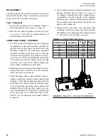
RE-ASSEMBLY
The following is a step-by-step procedure to be used to
assemble the chiller. Refer to
Installation Instruction
(Form 160.69-N3)
for other instructions.
Form 7 Shipment
1. Locate the evaporator and condenser shells in
their final position.
(See
2. Bolt the tube sheets together as shown in
Note that the outside surfaces of
the tube sheets must be flush.
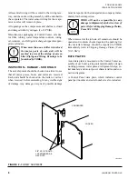
FORM 3 AND FORM 7 SHIPMENT
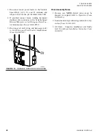
1. Level the shells in both directions. The longitudi-
nal alignment of the shell should be checked by
placing a level on the top of the shell, next to the
discharge connection. The transverse alignment
should be checked by placing a level on the tops
of both end sheets. Refer to
Installation Instruc-
tion (Form 160.69-N3)
for additional instructions
to level the unit. After the shell is leveled, wedge
and shim each corner of the shell to solidly sup-
port it while assembling the other parts.
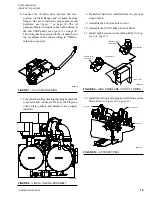
2. Discharge lines and suction lines should be sten-
ciled as "Drive #1" or "Drive #2". Correct orienta-
tion is necessary for proper fit.
3. Install discharge nozzle onto condenser heat ex-
changer connection using the proper gaskets and
hardware. Verify that the discharge pipe is level in
both directions. Install discharge isolation valve
n top of discharge pipe using proper gaskets and
hardware. Please note that the actuator valve uti-
lizes o-rings instad of a flat gasket. If utilizing any
oil on the o-ring, it's recommended that you use
York "K" oil. See discharge line weight in
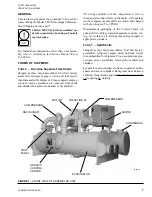
4. Lift a compressor/motor assembly and remove the
packing materials (refer to
for rigging). Carefully lower the compressor/mo-
tor assembly on to the supports on the condenser
discharge valve. Fasten with the proper hardware.
Do not tighten the bolts until all connections are
made to the compressor.
5. Install suction line nozzle onto evaporator heat
exchanger connection using the proper gaskets
and hardware. See discharge line weight in
8 - Suction/Discharge Piping on page 18
.
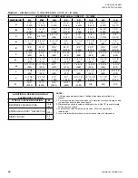
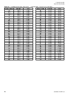
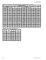
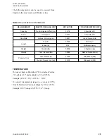
TABLE 6 -
COMPESSOR WEIGHTS
COMPRESSOR
ASSEMBLY
WEIGHT
LBS.
WEIGHT
KGS
K1
364-53357-201
4100
9020
K2
364-53362-201
4200
9240
K3
364-53348-201
6100
13420
K4
364-53349-201
6400
14080
K7
364-53350-201
8100
17820
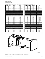
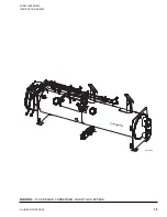
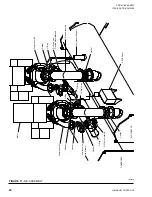
FIGURE 6 -
RIGGING – DRIVELINE ASSEMBLY
LD19863a


