


FORM 150.26-EG1 (116)
JOHNSON CONTROLS
23
FIELD WIRING
All field wiring must comply with the National Electric Code and all applicable local codes.
YORK liquid chiller units are factory wired for optimum reliability. Therefore the unit con-
trols must not be modified without ex pressed written consent by Johnson Controls. The
use of a simple switch or timer from a remote point is permitted; but it must be connected
to the unit panel at points expressly indicated for that purpose.
CONDENSER WATER
The chiller is engineered for maximum efficiency at both design and part-load operation
by taking advantage of the colder cooling tower water temperatures which naturally occur
during the winter months. Appreciable power savings are realized from these reduced
heads. For stable unit performance, continuous operation with entering condenser water
temperature below 65°F (18°C) is not recommended. For operation with entering con-
denser water temperature below this, it is recommended that some type of condenser
water temperature control be used.
REFRIGERANT RELIEF PIPING
Each chiller is equipped with pressure relief valves. The purpose of the relief valves is
to quickly relieve excess pressure of the refrigerant charge as a safety precaution in the
event of an emergency such as a fire. Sized to the requirements of applicable local codes,
a vent line must be run from the relief valve to the outside of the building. Vent piping must
be arranged to avoid imposing a strain on the relief valves and should include flexible
connections.
The low side relief valve is located on the suction line. It has a pressure setting of 400
psig (27.6 bar) and a capacity of 26.8 lbs. air/min ( 166.3 l/s). The high side relief valve
is located on the condenser shell. It has a pressure setting of 560 psig (38.6 bar) and a
capacity of 49.8 lbs air/min (309.1 l/s).
The 0064, 0074, and 0096 units have additional relief valves on the discharge line(s) in
lieu of compressor internal relief. The valve has a pressure setting of 650 psig (44.8 barg),
a capacity of 44.6 lbs air/min (277.0 l/s) and a 1/2” flare connection.
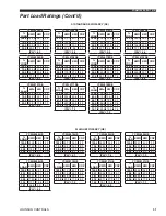
Application Data (Cont'd)
Содержание YCWL Series
Страница 4: ...JOHNSON CONTROLS FORM 150 26 EG1 116 4 THIS PAGE INTENTIONALLY LEFT BLANK ...
Страница 43: ...FORM 150 26 EG1 116 JOHNSON CONTROLS 43 Unit Dimensions Four Compressor Cont d ...
Страница 45: ...FORM 150 26 EG1 116 JOHNSON CONTROLS 45 Unit Dimensions Five Six Compressor Cont d ...
Страница 47: ...FORM 150 26 EG1 116 JOHNSON CONTROLS 47 Unit Dimensions SI Four Compressor Cont d ...
Страница 49: ...FORM 150 26 EG1 116 JOHNSON CONTROLS 49 Unit Dimensions SI Five Six Compressor Cont d ...
Страница 64: ...JOHNSON CONTROLS FORM 150 26 EG1 116 64 Typical Control Panel Wiring 4 COMPRESSOR UNITS LD18412 ...
Страница 65: ...FORM 150 26 EG1 116 JOHNSON CONTROLS 65 Typical Control Panel Wiring Cont d 4 COMPRESSOR UNITS ...
Страница 66: ...JOHNSON CONTROLS FORM 150 26 EG1 116 66 5 6 COMPRESSOR UNITS Typical Control Panel Wiring Cont d LD18413 ...
Страница 67: ...FORM 150 26 EG1 116 JOHNSON CONTROLS 67 Typical Control Panel Wiring Cont d 5 6 COMPRESSOR UNITS ...


