YORK INTERNATIONAL
12
FORM 201.25-NM1 (302)
POWER AND CONTROL PANELS
All controls and motor starting equipment are factory
wired and function tested. The panel enclosures are
designed to NEMA 1(IP33) and are manufactured from
powder painted galvanized steel.
The panel is divided into power sections for each elec-
trical system, a control section and a common input
section. Each section has separate hinged, latched, and
gasket sealed doors.
Each power section contains:
Compressor starting contactors, control circuit serving
compressor, compressor contactor coils and compres-
sor motor overloads.
The current transformers for the compressor motor
overloads sense each phase, as an input to the micro-
processor. This protects the compressor motors from
damage due to: low input current, high input current,
unbalanced current, single phasing, phase reversal, and
compressor locked rotor.
The control section contains:
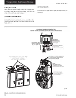
On/Off toggle switch, microcomputer keypad and dis-
play, microprocessor board (ARB), I/O expansion board
(AIOB), power supply board (APB) and customer ter-
minal block (-XTB1).
MICROPROCESSOR CONTROLS
The microprocessor has the following functions and
displays:
A liquid crystal 40 character display with text provided
on two lines and light emitting diode backlighting for
outdoor viewing.
A color coded, 35 button, sealed keypad with sections
for Display, Entry, Setpoints, Clock, Print, Program and
the unit Auto/Off switch.
The standard functions include: water or glycol cool-
ing, automatic pump down, demand load limiting from
external building automation system input, remote re-
set liquid temperature reset input, unit alarm and sta-
tus contacts, chilled liquid pump control, automatic re-
set after power failure, automatic system optimization
to match operating conditions.
The software is stored in non-volatile memory
(EPROM) to eliminate unit failure due to AC power
failure. The programmed setpoint is stored in a lithium
battery backed memory.
MOTOR CURRENT PROTECTION
The microprocessor motor protection provides high cur-
rent protection to assure that the motor is not damaged
due to voltage, excess refrigerant, or other problems
that could cause excessive motor current.
If the motor current exceeds the 115% FLA trip point
after 3 seconds of operation on Star/Delta starter, the
microprocessor will shut the system down and lock it
out after one fault. A manual reset of the respective
system switch is required to clear the fault and restart
the system. A thorough check of the motor, wiring, and
refrigerant system should be carried out before restart-
ing a system that has faulted on high motor current.
The microprocessor also provides low motor current
protection when it senses a motor current less than
10% FLA. Low motor current protection is activated 4
seconds after start on Star/Delta to allow the motor to
start. The microprocessor will shut the system down
whenever low motor current is sensed and will lock
out a system if three faults occur in 90 minutes. Once a
system is locked out on Low Motor Current, it must be
manually reset with the system switch.
The microprocessor also senses low motor current
whenever a High Pressure Cutout (HPCO) or Motor
Protector (MP) contact opens. The MP and HPCO con-
tacts are connected in series with the motor contactor.
Whenever either of these devices are open, the contactor
de-energizes and the motor shuts down. Since the mi-
croprocessor is sending a run signal to the contactor, it
senses the low motor current below 10% FLA and shuts
the system down.
Motor Protector Module
The mechanical motor protector module provides ther-
mal and current motor overload protection. This mod-
ule protects against phase to phase current imbalance,
over current, under current, and phase rotation. The
Product Description


