York YCAS Series Скачать руководство пользователя страница 4

YORK INTERNATIONAL

4

FORM 201.19-W3 (1104)
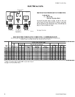
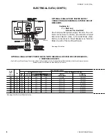
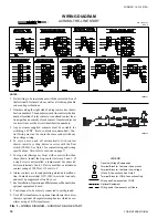
ELECTRICAL NOTES

ELECTRICAL NOTES

NOTES & LEGEND


LEGEND                                                                                                                                                                             

ACR-LINE                        ACROSS THE LINE START                                                                        
C.B.                                  CIRCUIT BREAKER                                                                                    
D.E.                                  DUAL ELEMENT FUSE                                                                               
DISC SW                          DISCONNECT SWITCH                                                                              
FACT CB                          FACTORY-MOUNTED CIRCUIT BREAKER                                               
FLA                                   FULL LOAD AMPS
HZ                                    HERTZ
MAX                                 MAXIMUM
MCA                                 MINIMUM CIRCUIT AMPACITY
MIN                                   MINIMUM
MIN NF                             MINIMUM NON-FUSED
RLA                                  RUNNING LOAD AMPS
S.P. WIRE                        SINGLE-POINT WIRING
Y-

                                   WYE-DELTA START

X-LRA                               ACROSS-THE-LINE INRUSH LOCKED ROTOR AMPS
Y-LRA                               WYE-DELTA INRUSH LOCKED ROTOR AMPS

VOLTAGE  CODE

   -50 = 380-3-50


NOTES

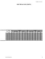
 1.    MRA is Maximum Running Amps, the maximum continuous current at any operating point in the rating range. Also referred to as MCA, or 

Minimum Circuit Ampacity to be provided by the installer. If a Factory Mounted Control Transformer is provided, add 3 amps to the system 
#1 MCA values in the YCAS Tables.

 2.    The recommended disconnect switch is based on a minimum of 115% of the summation rated load amps of all the loads included in the 

circuit, per N.E.C. 440 - 12A1.

 3.    Minimum recommended fuse size is based on 150% of the largest motor RLA plus 100% of the remaining RLAs. Minimum fuse rating = 

(1.5 x largest compressor RLA) + other compressor RLAs + (# fans x each fan motor FLA).

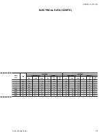
 4.    Maximum dual element fuse size is based on 225% maximum plus 100% of the rated load amps for all other loads included in the circuit, 

per N.E.C. 440-22. Maximum fuse rating  = (2.25 x largest compressor RLA) + other compressor RLAs + (# fans x each fan motor FLA).

 5.    Minimum recommended circuit breaker is 150% maximum plus 100% of rated load amps included in the circuit. Minimum circuit breaker 

rating = (1.5 x largest compressor RLA) + other compressor RLAs + (# fans x each fan motor FLA).

  6.    Maximum circuit breaker is based on 225% maximum plus 100% of the rated load amps for all loads included in the circuit, per circuit, per 

U.L. 

1995

 Fig. 36.2. Maximum circuit breaker rating = (2.25 x largest compressor RLA) + other com pres sor RLAs + ( # fans x each fan motor 

FLA).

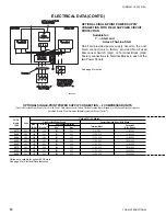
 7.    The Incoming Wire Range is the minimum and maximum wire size that can be accommodated by unit wiring lugs.  The (1), (2), or (3) 

indicate the number of termination points or lugs which are available per phase.  Actual wire size and number of wires per phase must be 
determined based on ampacity and job requirements using N.E.C. wire sizing information.  The above recommendations are based on the 
National Electrical Code and using 

copper connectors

 only. Field wiring  must also comply with local codes.

  8.    A ground lug is provided for each compressor system to accommodate fi eld grounding conductor per N.E.C. Article 250-54. A control circuit 

grounding lug is also supplied.

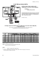
  9.    The fi eld supplied disconnect is a “Disconnecting Means” as defi ned in N.E.C. 100.B, and is intended for isolating the unit from the available 

power supply to perform maintenance and troubleshooting.  This disconnect is not intended to be a Load Break Device.

10.   Two-compressor machines with single-point power connection, and equipped with Star-Delta compressor motor start must also include 

Factory provided circuit breakers in each motor control center.

11.   Consult factory for Electrical Data on units equipped with “High Static Fan” option.  50Hz High Static Fans are 3.5kW each.

12.   FLA for each “Low Noise Fan” motor:   380v/50Hz = 4.1A.

Содержание YCAS Series

Страница 1: ...YCAS AIR COOLED LIQUID CHILLERS YCAS0373 THROUGH YCAS0653 STYLE G R22 50 Hz WIRING DIAGRAM AIR COOLED SCREW LIQUID CHILLERS New Release Form 201 19 W3 1104...

Страница 2: ...LIST OF FIGURES FIG 1 WIRING DIAGRAM ACROSS THE LINE START 14 FIG 2 WIRING DIAGRAM ACROSS THE LINE START 15 FIG 3 ELEMENTARY DIAGRAM ACROSS THE LINE START 16 FIG 4 WIRING DIAGRAM WYE DELTA START 18 FI...

Страница 3: ...uipment with power off take care to discharge every capacitor likely to hold dan gerous potential Be careful not to contact high voltage connections when installing or operating this equipment LOW VOL...

Страница 4: ...of rated load amps included in the circuit Minimum circuit breaker rating 1 5 x largest compressor RLA other compressor RLAs fans x each fan motor FLA 6 Maximum circuit breaker is based on 225 maximum...

Страница 5: ...YORK INTERNATIONAL 5 FORM 201 19 W3 1104 This page intentionally left blank...

Страница 6: ...1 60Hz POWER SUP PLY NOT REQUIRED IF OPTIONAL CONTROL TRANSFORMER FITTED OPTIONAL CONTROL TRANSFORMER SEE NOTE 3 SEE NOTE 3 0373 380 148 150 200 250 2 4 0 4 300 6 350 108 241 761 3 4 4 17 1 0403 380 1...

Страница 7: ...50 200 250 2 4 0 4 300 6 350 108 241 761 3 4 4 17 1 0403 380 160 200 200 250 2 4 0 4 300 6 350 118 241 761 3 4 4 17 1 0453 380 188 200 225 300 1 0 300 6 350 6 350 140 309 979 3 4 4 17 1 0503 380 215 2...

Страница 8: ...ler Field connections to Factory Provided Terminal Block standard or Non Fused Disconnect option Individual System Circuit Breakers in each Motor Control Center10 LD05549 Chiller FIELD SUPPLIED WIRING...

Страница 9: ...3 4 4 17 1 107 9 241 761 3 4 4 17 1 0403 380 117 7 241 761 3 4 4 17 1 117 7 241 761 3 4 4 17 1 0453 380 139 5 309 979 3 4 4 17 1 139 5 309 979 3 4 4 17 1 0503 380 161 3 309 979 3 4 4 17 1 161 3 309 9...

Страница 10: ...d or Non Fused Disconnect option No Internal Branch Circuit Protection Breakers per Motor Control Center10 See page 4 for notes LD05550 Chiller FIELD SUPPLIED WIRING Model Volts Field Provided Power S...

Страница 11: ...80 108 N A 761 3 4 4 17 1 108 N A 761 3 4 4 17 1 0403 380 118 N A 761 3 4 4 17 1 118 N A 761 3 4 4 17 1 0453 380 140 N A 979 3 4 4 17 1 140 N A 979 3 4 4 17 1 0503 380 161 N A 979 3 4 4 17 1 161 N A 9...

Страница 12: ...Wiring 2 The above recommendations are based on the National Electric Code and using copper connectors only Field wiring must also comply with local codes See page 4 for notes LD05551 Option not avai...

Страница 13: ...CODE 50 50 50 MAX kW 113 113 80 MAX AMPS 193 193 135 CONTROL POWER SUPPLY UNITS WITHOUT STANDARD CONTROL CIRCUIT TRANSFORMERS NO OF CONTROL MCA MAX DUAL NON FUSED COMPRESSORS POWER MAX LOAD ELEMENT D...

Страница 14: ...to cautions on page 17 5 To stop unit Emergency Stop with contacts other than those shown install the stop contact between 5 and 1 If a stop device is not installed a jumper must be connected between...

Страница 15: ...YORK INTERNATIONAL 15 FORM 201 19 W3 1104 LD09233 WIRING DIAGRAM CONT D ACROSS THE LINE START FIG 2 WIRING DIAGRAM ACROSS THE LINE START 035 15164 103 REV F SEE DETAIL C ON DRAWING 035 15164 102...

Страница 16: ...YORK INTERNATIONAL 16 FORM 201 19 W3 1104 ELEMENTARY DIAGRAM FIG 3 ELEMENTARY DIAGRAM ACROSS THE LINE START LD09480...

Страница 17: ...relay contactor coil Any contacts connected to flow switch inputs or BAS inputs on terminals 13 19 or TB3 or any other terminals must be sup pressed with a YORK P N 031 00808 000 suppressor across the...

Страница 18: ...g device in series with the flow switch FSLW See Note 3 for contact rating and wiring specifications Also refer to cautions on page 21 5 To stop unit Emergency Stop with contacts other than those show...

Страница 19: ...YORK INTERNATIONAL 19 FORM 201 19 W3 1104 WIRING DIAGRAM CONT D WYE DELTA START FIG 5 ELEMENTARY DIAGRAM WYE DELTA START LD09236...

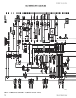
Страница 20: ...YORK INTERNATIONAL 20 FORM 201 19 W3 1104 ELEMENTARY DIAGRAM FIG 6 ELEMENTARY DIAGRAM WYE DELTA START LD09480...

Страница 21: ...low switch for start stop into the Alarm circuitry or pilot relays for pump starters wired through motor contactor auxiliary con tacts must be suppressed with YORK P N 031 00808 000 suppressor across...

Страница 22: ...YORK INTERNATIONAL 22 FORM 201 19 W3 1104 FIG 7 POWER PANEL SYSTEM 1 COMPONENT LOCATIONS LD09238 POWER PANEL SYSTEM 1 035 18672 104 REV E...

Страница 23: ...YORK INTERNATIONAL 23 FORM 201 19 W3 1104 LD010026 FIG 8 CONTROL PANEL COMPONENT LOCATION CONTROL PANEL 035 18672 104 REV E...

Страница 24: ...YORK INTERNATIONAL 24 FORM 201 19 W3 1104 FIG 9 POWER PANEL SYSTEM 2 COMPONENT LOCATIONS LD09240 POWER PANEL SYSTEM 2 035 18672 104 REV E...

Страница 25: ...YORK INTERNATIONAL 25 FORM 201 19 W3 1104 LEGEND LD010027...

Страница 26: ...YORK INTERNATIONAL 26 FORM 201 19 W3 1104 LD03282 LD03283 LD03284 035 15164 102 REV E...

Страница 27: ...YORK INTERNATIONAL 27 FORM 201 19 W3 1104 CONNECTION DIAGRAM SYSTEM WIRING LD09242 FIG 10 CONNECTION DIAGRAM SYSTEM WIRING...

Страница 28: ...YORK INTERNATIONAL 28 FORM 201 19 W3 1104 COMPRESSOR TERMINAL BOX LD09243 FIG 11 COMPRESSOR TERMINAL BOX 035 18672 105 REV A...

Страница 29: ...YORK INTERNATIONAL 29 FORM 201 19 W3 1104 LD010028 ELEMENTARY DIAGRAM STARTER CONTROL CIRCUIT FIG 12 ELEMENTARY DIAGRAM STARTER CONTROL CIRCUIT 035 15164 102 REV E...

Страница 30: ...3 4 5 6 3 4 5 6 7 8 5 6 3 4 7 8 9 10 LD06840 ELEMENTARY DIAGRAM FAN CONTROL FIG 13 ELEMENTARY DIAGRAM FAN CONTROL CIRCUIT 035 15164 102 REV E...

Страница 31: ...YORK INTERNATIONAL 31 FORM 201 19 W3 1104 NOTES...

Страница 32: ...1001 www york com P O Box 1592 York Pennsylvania USA 17405 1592 Subject to change without notice Printed in USA Copyright by York International Corporation 2004 ALL RIGHTS RESERVED Form 201 19 W3 1104...

Отзывы: