YORK INTERNATIONAL
78
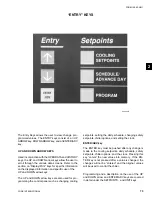
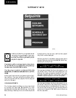
PROGRAM key
There are six operating parameters under the PRO-
GRAM key that are programmable. These setpoints can
be changed by pressing the PROGRAM key, and then
the ENTER/ADV key to enter
Program Mode. Continu-
ing to press the ENTER/ADV key will display each op-
erating parameter. While a particular parameter is be-
ing displayed, the UP and DOWN arrow keys can be
used to change the value. After the value is changed,
the ENTER/ADV key must be pressed to enter the data
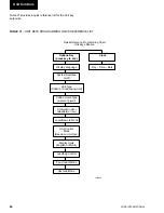
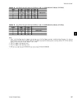
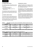
into memory. Table 29 shows the programmable limits
and default values for each operating parameter.
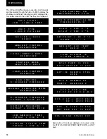
Following are the displays for the programmable val-
ues in the order they appear:
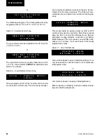
DISCHARGE PRESSURE CUTOUT is the discharge
pressure at which the system will shutdown as moni-
tored by the
optional discharge transducer. This is a
software shutdown that acts as a backup for the me-
chanical high pressure switch located in the refrigerant
circuit. The system can restart when the discharge pres-
sure drops 40 PSIG (2.76 BARG) below the cutout point.
If the optional discharge pressure transducer is not in-
stalled, this programmable safety would not apply. It
should be noted that every system has a
mechanical
high pressure cutout that protects against excessive high
discharge pressure regardless of whether or not the op-
tional discharge pressure is installed.
The SUCTION PRESSURE CUTOUT protects the
chiller from an evaporator freeze-up. If the suction pres-
sure drops below the cutout point, the system will shut
down.
There are some exceptions when the
suction pressure is permitted to tem-
porarily drop below the cutout point.
Details are explained under the topic
of System Safeties.
The LOW AMBIENT TEMP CUTOUT allows the user
to select the chiller outside ambient temperature cutout
point. If the ambient falls below this point, the chiller will
shut down. Restart can occur when temperature rises
2°F (1.11°C) above the cutout setpoint.
The LEAVING LIQUID TEMP CUTOUT protects the
chiller from an evaporator freeze-up. Anytime the leav-
ing chilled liquid temperature drops to the cutout point,
the chiller shuts down. Restart will be permitted when
the leaving chilled liquid temperature rises 2°F (1.11°C)
above the cutout setpoint.
When water cooling mode is programmed (Options key),
the value is fixed at 36.0°F (2.22°C) and cannot be
changed. Glycol cooling mode can be programmed to
values listed in Table 28.
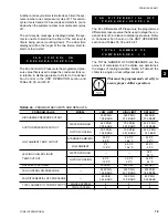
The anti-recycle timer message shows the amount of
time left on the respective systems anti-recycle timer.
The programmed ANTI RECYCLE TIME will start to
count down at the start of the systems number one com-
pressor. In effect, this is the minimum time start-to-start
on the respective systems number one compressor.
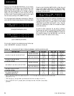
@
D I S C H A R G E
P R E S S U R E
C U T O U T
=
3 9 5
P S I G
L O W
A M B I E N T
T E M P
C U T O U T
=
2 5 . 0 ° F
L E A V I N G
L I Q U I D
T E M P
C U T O U T
=
3 6 . 0 ° F
S U C T I O N
P R E S S U R E
C U T O U T
=
4 4 . 0
P S I G
A N T I
R E C Y C L E
T I M E
=
6 0 0
S E C
Unit Controls
Содержание YCAL0014SC
Страница 112: ...YORK INTERNATIONAL 112 ELEMENTARY DIAGRAM YCAL0014SC YCAL0030SC FIG 11 ELEMENTARY DIAGRAM Wiring Diagrams...
Страница 114: ...YORK INTERNATIONAL 114 ELEMENTARY DIAGRAM YCAL0014SC YCAL0030SC LD03532 FIG 12 ELEMENTARY DIAGRAM Wiring Diagrams...
Страница 115: ...YORK INTERNATIONAL 115 FORM 150 62 NM1 This page intentionally left blank 4...
Страница 116: ...YORK INTERNATIONAL 116 ELEMENTARY DIAGRAM YCAL0034SC FIG 13 ELEMENTARY DIAGRAM Wiring Diagrams...
Страница 117: ...YORK INTERNATIONAL 117 FORM 150 62 NM1 FIG 13 ELEMENTARY DIAGRAM Cont d LD03533 ELEMENTARY DIAGRAM YCAL0034SC 4...
Страница 118: ...YORK INTERNATIONAL 118 FIG 14 ELEMENTARY DIAGRAM ELEMENTARY DIAGRAM YCAL0034SC LD03534 Wiring Diagrams...
Страница 119: ...YORK INTERNATIONAL 119 FORM 150 62 NM1 This page intentionally left blank 4...
Страница 120: ...YORK INTERNATIONAL 120 ELEMENTARY DIAGRAM YCAL0040SC YCAL0060SC FIG 15 ELEMENTARY DIAGRAM Wiring Diagrams...
Страница 122: ...YORK INTERNATIONAL 122 ELEMENTARY DIAGRAM YCAL0040SC YCAL0060SC FIG 16 ELEMENTARY DIAGRAM Wiring Diagrams...
Страница 124: ...YORK INTERNATIONAL 124 ELEMENTARY DIAGRAM YCAL0064SC YCAL0080SC FIG 17 ELEMENTARY DIAGRAM Wiring Diagrams...
Страница 126: ...YORK INTERNATIONAL 126 ELEMENTARY DIAGRAM YCAL0064SC YCAL0080SC FIG 18 ELEMENTARY DIAGRAM Wiring Diagrams...
Страница 130: ...APPENDIX 1 DIMENSIONS FIG 19 TYPE CP 1 FIG 20 TYPE CP 2 LD03839 LD03840 Appendix 1 Isolators...
Страница 135: ...YORK INTERNATIONAL 135 FORM 150 62 NM1 This page intentionally left blank...


