


YORK INTERNATIONAL
75
FORM 150.62-NM1
After using the UP and DOWN arrows to adjust to the
desired setpoint, the ENTER/ADV key must be pressed
to enter this number into memory and advance to the
RANGE SETPOINT.
This will be indicated by the cursor moving under the
current RANGE setpoint. The UP and DOWN arrow keys
are used to set the RANGE, in .5 °F increments, to the
desired RANGE setpoint. After adjusting the setpoint,
the ENTER/ADV key must be pressed to enter the data
into memory.
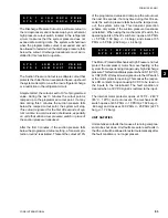
Notice that the RANGE was programmed for
+/- X.X° F.
This indicates the SETPOINT to be in the
center of the
control range. If the control mode has been programmed
for RETURN LIQUID control, the message below would
be displayed in place of the previous message.
(return chilled liquid control)
Notice that the range no longer has a
+/- X.X °F, but only
a
+ X.X °F RANGE setpoint. This indicates that the
setpoint is not centered within the RANGE but could be
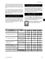
described as the bottom of the control range A listing of
the limits and the programmable values for the COOL-
ING SETPOINTS are shown in Table 27.
The SETPOINT and RANGE displays just described
were based on LOCAL control. If the unit was pro-
grammed for REMOTE control (under the OPTIONS
key), the above programmed setpoints would have no
effect.
Both LEAVING and RETURN control are described in
detail under the section on Capacity Control.
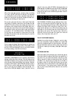
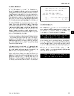
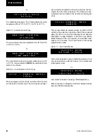
This message indicates that the cooling setpoint is un-
der REMOTE control. When under remote control, the
cooling setpoint will be determined by a remote device
such as an ISN control. The message also indicates
that the control point is based on LEAVING water tem-
perature out of the evaporator.
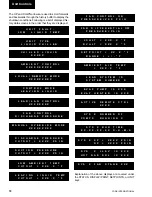
This message indicates that the cooling setpoint is un-
der REMOTE control. When under remote control, the
cooling setpoint will be determined by a remote device
such as an ISN control. This message also indicates
that the control point is based on RETURN water tem-
perature into the evaporator.
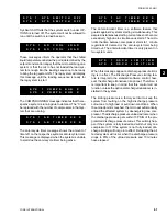
Immediately after the control mode message is dis-
played, the COOLING SETPOINT entry screen will be
displayed. If the unit is programmed for LEAVING liquid
control the following message will be displayed:
(leaving chilled water control)
The above message shows the current chilled water tem-
perature SETPOINT at 45.0°F (notice the cursor posi-
tioned under the number 5). Pressing either the UP or
DOWN arrow will change the setpoint in .5°F increments.
R E M 0 T E
L E A V I N G
W A T E R
T E M P
C O N T R O L
S E T P O I N T
=
4 5 . 0 ° F
R A N G E
=
+/-
2 . 0 ° F
R E M O T E
R E T U R N
W A T E R
T E M P
C O N T R O L
S E T P O I N T
=
4 5 . 0
° F
R A N G E
=
+ 2 . 0 ° F
2
Содержание YCAL0014SC
Страница 112: ...YORK INTERNATIONAL 112 ELEMENTARY DIAGRAM YCAL0014SC YCAL0030SC FIG 11 ELEMENTARY DIAGRAM Wiring Diagrams...
Страница 114: ...YORK INTERNATIONAL 114 ELEMENTARY DIAGRAM YCAL0014SC YCAL0030SC LD03532 FIG 12 ELEMENTARY DIAGRAM Wiring Diagrams...
Страница 115: ...YORK INTERNATIONAL 115 FORM 150 62 NM1 This page intentionally left blank 4...
Страница 116: ...YORK INTERNATIONAL 116 ELEMENTARY DIAGRAM YCAL0034SC FIG 13 ELEMENTARY DIAGRAM Wiring Diagrams...
Страница 117: ...YORK INTERNATIONAL 117 FORM 150 62 NM1 FIG 13 ELEMENTARY DIAGRAM Cont d LD03533 ELEMENTARY DIAGRAM YCAL0034SC 4...
Страница 118: ...YORK INTERNATIONAL 118 FIG 14 ELEMENTARY DIAGRAM ELEMENTARY DIAGRAM YCAL0034SC LD03534 Wiring Diagrams...
Страница 119: ...YORK INTERNATIONAL 119 FORM 150 62 NM1 This page intentionally left blank 4...
Страница 120: ...YORK INTERNATIONAL 120 ELEMENTARY DIAGRAM YCAL0040SC YCAL0060SC FIG 15 ELEMENTARY DIAGRAM Wiring Diagrams...
Страница 122: ...YORK INTERNATIONAL 122 ELEMENTARY DIAGRAM YCAL0040SC YCAL0060SC FIG 16 ELEMENTARY DIAGRAM Wiring Diagrams...
Страница 124: ...YORK INTERNATIONAL 124 ELEMENTARY DIAGRAM YCAL0064SC YCAL0080SC FIG 17 ELEMENTARY DIAGRAM Wiring Diagrams...
Страница 126: ...YORK INTERNATIONAL 126 ELEMENTARY DIAGRAM YCAL0064SC YCAL0080SC FIG 18 ELEMENTARY DIAGRAM Wiring Diagrams...
Страница 130: ...APPENDIX 1 DIMENSIONS FIG 19 TYPE CP 1 FIG 20 TYPE CP 2 LD03839 LD03840 Appendix 1 Isolators...
Страница 135: ...YORK INTERNATIONAL 135 FORM 150 62 NM1 This page intentionally left blank...


