


JOHNSON CONTROLS
65
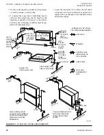
SECTION 3 - HANDLING, STORAGE, AND INSTALLATION
FORM 102.20-N1
ISSUE DATE: 7/06/2016
3
GENERAL ELECTRICAL INFORMATION
All field wiring must conform to the
International Building Codes (IBC),
National Electrical Code (NEC) and
local codes.
The AHU is ETL listed. Some compo
-
nents are UL labeled. Any changes in the
field may affect its validity.
The current characteristics of phase, cycle and voltage
are stamped on the nameplate of each component. Use
the following instructions to set up the electrical con-
nections.
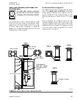
•
Install electrical conduit connections, which are
made to exposed boxes, to the bottom of the box.
Outdoor installation must be made watertight.
The installing contractor is responsible for electri-
cal conduit penetrations through the building roof.
•
Seal the penetrations through the panels.
•
Externally and internally seal the electrical con-
duits that penetrate the AHU exterior (walls, pipe
chase or floors) so that the unconditioned air will
not be drawn into the AHU through and around
the conduit. Unconditioned air will result in con-
densation that will fail components prematurely.
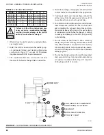
•
Check all accessible electrical connections, which
contain several strands of wire, for tightness prior
to start-up. The wires are tightened at the time of
assembly, but check, and retighten them, if neces-
sary. The dangers of a poor connection are over-
heating and component failure.
DO NOT PENETRATE any main or aux
-
iliary drain pan or roof of outdoor AHU.
DO NOT PENETRATE wireways in any
manner. The sheet metal channels, which
run along the top panel, contain electrical
wires and connections. Electrical shock
and/or damage to the AHU may result.
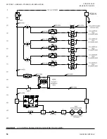
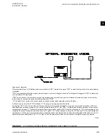
Electrical drawings are provided in the information
packet on the inside of the AHU access door. Major
optional components will have specific electrical and
installation information inside the control panels or
will be attached. Refer to
SECTION 5 - WIRING DI-
AGRAMS
in the
Air Handling Units - Operation and
Maintenance Manual (Form 102.20-OM2)
for more
information on the electrical drawings.
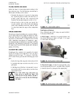
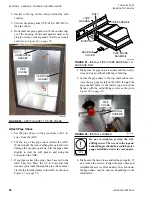
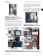
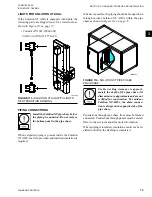
POWER CONNECTIONS
Single Point Power
When ordered, the single point power connection pro-
vides the installer with a main disconnect switch as
shown in
. The line side of
this switch (top) is where the installer is to connect his
main power wires. The devices included in the single
point power option are :
•
Supply, Return, and Exhaust Fans
•
Energy Recovery Wheel
•
Gas and Electric Heat
•
Ultra-violet Lights
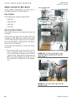
FIGURE 99 -
SINGLE POINT POWER
CONNECTION
LD16607
Special quoted devices not included in this option may
be purchased with the AHU, and will require separate,
additional power wiring by the installer. When this op-
tion is NOT purchased, the installer is responsible for
wiring to each electrical component.


