background image

84

YORK INTERNATIONAL

LD02102

OPTIONAL DECORATIVE TAMPERPROOF

ENCLOSURE (LOUVERED & WIRE GRILLE)

General

A combination louvered and wire grille enclosure is avail-

able for the chiller for the prime purpose of deterring un-

authorized access to components of the chiller.

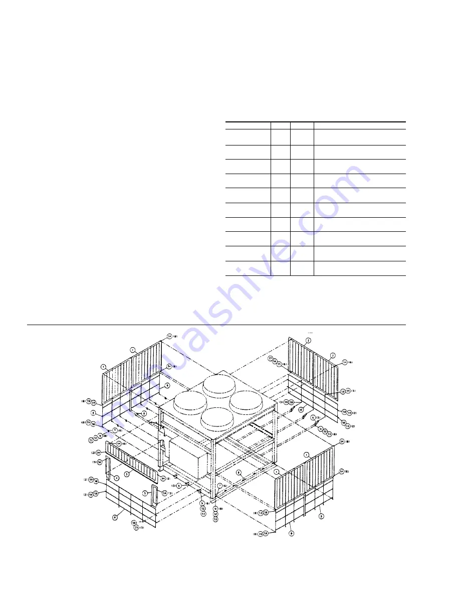
Kit 475-04559-002 is the decorative/tamperproof enclo-

sure which consists of a combination of louvered sheet

metal panels and weather resistant wire grilles along with

mounting hardware. This kit has a further purpose of pre-

senting a pleasing appearance to the chiller when it is

located in a highly visible area.

Installation

1. Refer to Fig. 37 and the associated parts list. Before

starting installation, all of the items in the kit should

be identified by comparing with Fig. 37.

2. All holes for mounting kit parts are provided in both

the chiller frame and the added supports; therefore,

it should be unnecessary to drill holes.

3. Install the louvered panels and wire grilles using the

proper hardware and supports. Refer to Fig. 37 and

the Parts List for placement of the grilles/panels and

the proper hardware required. Discard existing grilles

to attach the louvered panels where necessary.

4. Notch grilles to suit water connection and wiring har-

nesses as needed.

5. If the High Ambient Sunshield Kit or Disconnect Op-

tion is installed, field adaption will be required where

parts of the kits interfere. Touch up exposed metal

parts to prevent rust.

NOTES:

1.  Notch grilles to suit water connections and wiring harnesses.

2.  Discard existing grilles to attach louver panels where necessary.

FIG. 37 –

 LOUVERED AND WIRE GRILLE INSTALLATION

Parts List

PART #

ITEM QUAN.

DESCRIPTION

075-02563-002

1

4

Panel, Louvers Side Top

075-02563-005

2

2

Panel, Louvers Rear Top

075-02563-015

3

1

Panel, Louvers Front Top R.H.

075-02563-016

4

1

Panel, Louvers Front Top L.H.

075-02563-017

5

1

Panel, Louvers Front Top

075-02501-000

6

5

Bracket

075-02502-000

7

12

Clip, Retainer

075-02503-000

8

2

Clip, Retainer

026-31634-000

9

4

Grille, Side Btm.

026-32206-000

10

1

Grille, Rear Btm.

026-32207-000

11

1

Grille, Front Btm.

021-16205-000

51

28

Screw, Cap Hex 3/8-16 x 1/2

021-16158-000

52

28

Lock Washer Spg. 3/8

021-16139-000

53

28

Nut, Hex 3/8

021-16136-000

54

54

Screw, Tap Cut 1/4 x 1/2

021-16161-000

55

6

Screw, Cap Hex 1/4-20 x 3/4

021-16210-000

56

6

Lock Washer Spg. 1/4

021-16151-000

57

6

Nut, Hex 1/4

021-16203-000

58

49

Screw, Tap Type “F” 1/4 x 3/4 Lg.

021-16165-000

59

49

Washer, Flat 1/4

Содержание RecipPak YEAJ44DR6

Страница 1: ...T8 YEAJ65HT8 YEAJ66MT8 50 HZ MODELS YEAJ44DR7 YEAJ55DR7 YEAJ55HT7 YEAJ65ES7 YEAJ66HT9 YEAJ76HT9 YEAJ77MT9 STYLE A With EPROM 031 01096 001 Standard Brine Metric Models Combined 200 230 460 3 60 M A N U F A C T U R E R C ERTIFIED TO ARI AS C O M P L Y I N G W I T H A RI STANDARD 430 C E N T R A L S T ATION AIR H A N D L I N G UNITS 26174A SHOWN WITH OPTIONAL SINGLEPOINTPOWERCONNECTION ...

Страница 2: ...rily for central station air conditioning applications with normal installations being on roof tops or on ground level beside the building CODE STATUS The units are designed in accordance with UL 200 230 460 3 60 N E C ASHRAE ANSI STANDARD 15 and ASME Codes ARI 590 GENERAL INFORMATION Y E A J 5 4 H T 8 46 P A YORK S Special Blank if not used Chiller Design Level Air Cooled Type Start Compressor Ty...

Страница 3: ...3 60 28 230 3 60 40 380 3 60 46 460 3 60 50 380 415 3 50 58 575 3 60 64 346 3 50 Motor Manufacturer S A O Smith L Leroy Somer J G 4 3 1 M 17 S COMPRESSOR NOMENCLATURE Compressor Series No of Active Cylinders 4 6 Displacement No of Steps of Unloading 0 1 2 Style B Motor Size Code Electrical Voltage Code Motor Vendor S A O Smith L Leroy Somer Z 6 W 2 B E 46 S Z MODELS J MODELS ...

Страница 4: ... GLASS TX VALVE SIGHT GLASS TXV SYSTEM 1 25212A 26174A UNIT DATA PLATE SIDE OF PANEL MICROPANEL CONDENSER FANS CONDENSER COIL S POWER PANEL COMPRESSOR 2 COMPRESSOR 1 OPTIONALSINGLE POINTPOWERCONNECT COMPRESSOR POWERSUPPLY COOLER 25211A SYSTEM 2 SOLENOID VALVE SYSTEM 1 LIQUIDSTOP VALVE SYSTEM 2 LIQUIDSTOP VALVE SYSTEM 2 FILTER DRIER SYSTEM 1 FILTER DRIER ...

Страница 5: ...FORM 150 60 NM4 YORK INTERNATIONAL 5 26068A 26069A FIG 1 UNIT COMPONENTS Cont d INTERIOR VIEW POWER PANEL SINGLEPOINT CONNECTION TERMINALS GROUND LUGS ...

Страница 6: ...MPRESSOR OIL CHARGING VALVE 27294A DISCHARGE STOP VALVE TERMINAL BOX CAPACITY CONTROL SOLENOID OIL PRESURE ACCESSCONN OIL LEVEL SIGHT GLASS CRANKCASE HEATER OIL PUMP DATA PLATE DISCHARGE STOP VALVE CAPACITY CONTROL SOLENOIDS SUCTIONPRESSURE CONNECTION RAINTIGHT TERMINALBOX SUCTION STOP VALVE SIGHT GLASSES 2 OILCHARGING VALVE CRANKCASE HEATER OILPRESSURE ACCESS CONNECTION 27599A ...

Страница 7: ...uires the Optional Low Ambient kit 3 Operation above 115 F requires Optional High Ambient kit MODEL LVG WATER COOLER4 AIRON YEA TEMP F GPM CONDENSER F MIN 1 MAX MIN MAX MIN 2 MAX 3 Z88DR6 J44DR1 40 50 120 580 0 130 J44DR6 J55DR7 40 50 120 580 0 130 J44HT6 J55HT7 40 50 150 640 0 130 J54ES6 J65ES7 40 50 120 580 0 130 J55HT8 J66HT9 40 50 150 640 0 130 J65HT8 J76HT9 40 50 150 640 0 130 J66MT8 J77MT9 4...

Страница 8: ...tended and snow accumulations are expected additional unit height must be provided to insure full air flow 2 VIBRATION ISOLATORS optional will increase overall height of unit by approx 6 3 Drawings not to scale and are for planning purposes only Contact nearest YORK office for detail drawings DIMENSIONS MODEL WEIGHTDISTRIBUTIONS LBS NOZZLESIZE YEA A B C D E INLET OUTLET Z88DR6 2194 1911 2202 1982 ...

Страница 9: ...4 4 1140 RPM 60 HZ 3 2 4 3 2 4 3 2 4 3 2 4 5 3 8 5 3 8 5 3 8 HP KW Each 950 RPM 50 HZ 3 2 2 3 2 2 3 2 2 3 2 2 5 4 1 5 4 1 5 4 1 CFM Total 60 HZ 62 200 62 200 60 000 61 100 71 600 71 600 71 600 50 HZ 61 700 61 700 58 600 60 100 71 100 71 100 71 100 COOLER DUAL CIRCUITED DWP 235 PSIG REF SIDE 14 x8 14 x8 16 x8 14 x8 16 x8 16 x8 20 x8 150 PSIG WATER SIDE DlA x LENGTH WATER VOLUME GALS 38 38 39 36 39 ...

Страница 10: ... 1 250MCM J55DR7 64 325 400 450 400 450 1 3 6 350MCM 1 1 600MCM OR 2 1 250MCM J44HT6 17 558 700 700 600 700 1 3 6 350MCM 1 2 4 0 500MCM J44HT6 28 499 600 600 600 600 1 3 6 350MCM 1 2 4 0 500MCM J44HT6 40 294 350 400 400 400 1 6 350MCM 1 1 600MCM OR 2 1 250MCM J44HT6 46 246 300 300 400 300 1 6 350MCM 1 1 600MCM OR 2 1 250MCM J55HT7 50 199 350 400 400 400 1 6 350MCM 1 1 600MCM OR 2 1 250MCM J44HT6 5...

Страница 11: ...5 1 2 4 250MCM 254 80 4 9 180 225 300 200 450 1 2 4 250MCM 412 134 5 8 180 225 300 200 300 1 2 4 250MCM 412 134 5 8 308 400 500 400 700 1 2 4 250MCM 731 230 10 0 308 400 500 400 500 1 2 4 250MCM 731 230 10 0 275 350 450 400 600 1 2 4 250MCM 636 200 12 0 275 350 450 400 450 1 2 4 250MCM 636 200 12 0 162 200 250 200 400 1 2 4 250MCM 385 121 5 2 162 200 250 200 250 1 2 4 250MCM 385 121 5 2 136 175 22...

Страница 12: ...12 YORK INTERNATIONAL DUAL COMPRESSOR POWER SUPPLY WIRING STANDARD UNIT NON FUSED DISCONNECT OPTION SINGLE POINT OPTION LD02072 LD02073 LD02074 See Notes on page 10 ...

Страница 13: ...amage due to rough handling The units are shipped without export crating unless it is specified by Sales Order A unit should be lifted by inserting hooks through the holes provided in unit base rails Spreader bars should be used to avoid crushing the unit with the lifting chains See Fig 3 INSPECTION Immediately upon receiving the unit it should be in spected for possible damage which may have occu...

Страница 14: ... 27 402237 22 Cu Cu 12 650 13 250 3349 CP 4 28 3045 CP 4 28 3541 CP 4 28 3305 CP 4 28 402237 20 J77MT9 Cu AI 11 650 12 250 3127 CP 4 28 2822 CP 4 27 3261 CP 4 28 3024 CP 4 27 402237 41 Cu Cu 13 000 13 600 3468 CP 4 28 3163 CP 4 28 3602 CP 4 28 3366 CP 4 28 402237 20 Ground Level Locations It is important that the units be installed on a substantial base that will not settle A one piece concrete sl...

Страница 15: ...8 Orange 1 06 26 9 CP 4 28 3600 1632 9 Green 1 02 25 9 CP 4 31 4400 1995 8 Gray 83 21 0 CP 4 32 5200 2358 7 White 74 18 7 CP 4 35 6000 2721 6 Gold 70 17 7 COMPRESSOR MOUNTING The compressors are mounted on four 4 isolator pads one under each compressor foot See Fig 4 The mounting bolts are not to be loosened or adjusted at installation CHILLED LIQUID PIPING GENERAL When the unit has been located i...

Страница 16: ...d to prevent forma tion of condensation on lines in warm humid climates 7 A chilled water flow switch either by YORK or oth ers MUST be installed in the leaving water piping of the cooler There should be a straight horizontal run of at least 5 diameters on each side of the switch Adjust the flow switch paddle to the size of pipe in which it is to be installed See manufacturer s in structions furni...

Страница 17: ...DC Gold contacts recommended Wiring shall not be run in the same conduit with any line voltage wiring 4 To cycle unit on and off automatically with contact shown install a cycling device in series with the flow switch FLSW See Note 3 for contact rating and wiring specifications 5 To stop unit Emergency Stop with contacts other than those shown install the stop contact between 5 and 1 If a stop dev...

Страница 18: ...lt in nui sance faults CAUTION Any inductive devices relay wiredinserieswith the flow switch for start stop into the Alarm cir cuitry or pilot relays for pump starters wired through motor contactor auxiliary contacts must be suppressed with YORK P N 301 00808 suppressor across the relay contactor coil which activates the con tacts Any contacts connected to flow switch inputs or BAS inputs on termi...

Страница 19: ...FORM 150 60 NM4 YORK INTERNATIONAL 19 FIG 5 SYSTEM WIRING LD02080 LD02082 LD02081 CONNECTION DIAGRAM SYSTEM WIRING YEA 95 160 CONDENSER FANS COOLER COMPRESSORS ...

Страница 20: ...20 YORK INTERNATIONAL LD02083 COMPRESSOR TERMINAL BOX SYSTEM NO 1 COMPRESSOR TERMINAL BOX SYSTEM NO 2 FIG 6 SYSTEM WIRING Cont d ...

Страница 21: ...FORM 150 60 NM4 YORK INTERNATIONAL 21 LD02084 CONNECTION DIAGRAM ELECTRICAL BOX YEA 95 160 FIG 7 CONNECTION DIAGRAM ...

Страница 22: ...22 YORK INTERNATIONAL LD02086 LD02085 LD02087 FIG 7 CONNECTION DIAGRAM Cont d ...

Страница 23: ...d chilled water tempera ture reset can be accomplished by user supplied dry contacts Compressor starting stopping and loading unloading de cisions are performed by the Microprocessor to main tain leaving water temperatures These decisions are a function of temperature deviation from setpoint and rate of change of temperature MICROPROCESSOR BOARD The Microprocessor Board is the controller and decis...

Страница 24: ... be at 12VDC potential CURRENT TRANSFORMER C T A C T on the 3φ power wiring of each motor sends AC signals proportional to motor current to the Power Sup ply Board which rectifies and filters the signal to variable DC voltage analog This analog level is then fed to the Microprocessor Board to allow it to monitor motor cur rent 40 CHARACTER DISPLAY The 40 Character Display 2 lines of 20 characters ...

Страница 25: ...CONTROL PANEL EXTERIOR MICROPROCESSOR BOARD KEYPAD TB3 26000A LCD DISPLAY BOARD MICROPROCESSOR BOARD UNITON OFF SWITCH 2TTRANSFORMER RELAY OUTPUT BOARD 1 TB3 CONNECTIONS FOR FLOW SWITCH LEAD LAG SELECTORAND EMS BAS CONTROLS LOCATION OF OPTIONAL RELAY OUTPUT BOARD 2 POWERSUPPLY BOARD ...

Страница 26: ...layed If a message is required to be updated faster than every 2 seconds the appropriate key for the desired display may be pushed and held Updating will be at 4 second intervals Each of the keys and an example of the typical corre sponding display messages will be discussed in the text which follows DISPLAY KEYS Discharge Pressure Readout is an option Without this option the display will read a f...

Страница 27: ... have been selected by the user These options are se lected by the S1 Dip Switch on the Microprocessor Board Fig 12 Proper programming of the switch is important during commissioning of the chiller The OPTIONS dis play allows a means of verifying the Dip Switch posi tions without looking at or handling the Microprocessor Board It also eliminates visual inspection of the some times difficult to det...

Страница 28: ...A R G E P R E S S U R E F A N C O N T R O L M A N U A L L E A D L A G A U T O M A T I C L E A D L A G S T A N D A R D C O N D E N S E R F A N C O N T R O L S H A R E D C O N D E N S E R F A N C O N T R O L E N G L I S H U N I T S R E A D O U T M E T R I C U N I T S R E A D O U T R E T U R N W A T E R C O N T R O L L E A V I N G W A T E R C O N T R O L L O C A L C O N T R O L M O D E R E M O T E C ...

Страница 29: ...25 F CLOSED The low ambient cut out is programmable from 0 50 F A low ambient kit MUST be installed if the switch is placed in this position SWITCH 3 OPEN DO NOT USE this mode at present CLOSED This should be selected in all applications otherwise printer communication problems may result This mode will also be necessary to allow operation of options to be developed in the future Positioning of th...

Страница 30: ...is mode maximum chiller efficiency will be achieved If the Low Ambient option is installed the fan control will automatically change to pressure control at tempera tures below 25 F See page 68 for fan control sequence CLOSED Fan control is by discharge pressure only This mode of fan control will increase discharge pressure It should be used if nuisance low suction pressure faults are experi enced ...

Страница 31: ... KEY The DAILY SCHEDULE SHUTDOWN message indicates that the schedule programmed into the CLOCK SET SCHEDULE HOLIDAY is keeping the chiller from run ning Run Permissive is an indicator that an external cycling contact i e flow switch connected to terminals 13 and 14 is open or a system switch es on the Microproces sor Board is in the OFF position Whenever the contact is open or a switch is OFF the ...

Страница 32: ... discharge pres sure has exceeded the user programmable threshold and the micro is unloading the affected system to prevent shutdown on a manual high pressure cut out Reloading will take place when discharge pressure has dropped 60 PSIG below the threshold Optional discharge pressure transducers must be in stalled for this feature to operate This is accomplished by adding the Discharge Pressure Re...

Страница 33: ...E R T E M P S Y S 2 H I G H D S C H C H I L L E R F A U L T H I G H A M B I E N T T E M P S Y S 1 L O W O I L P R E S S C H I L L E R F A U L T 1 1 5 V A C U N D E R V O L T A G E S Y S 2 L O W O I L P R E S S S Y S 1 L O W S U C T I O N S Y S 2 L O W S U C T I O N S Y S 1 M O T O R C U R R E N T S Y S 2 M O T O R C U R R E N T S Y S 1 L L S V N O T O N S Y S 2 L L S V N O T O N ...

Страница 34: ...rough available data after any one of the following keys is pressed PROGRAM SET SCHEDULE HOLIDAY OPER DATA HISTORY Cancel Key The CANCEL key allows the user to change errors in the data being programmed into memory When the CANCEL key is pressed any data which has been keyed in but not entered will be erased The origi nal values will re appear on the display and the cursor will return to the first...

Страница 35: ... CHECKED AND PROPERLY PRO GRAMMED WHEN COMMISSIONING THE CHILLER FAILURE TO PROPERLY PROGRAM THESE VALUES MAY CAUSE DAMAGE TO THE CHILLER OR OPERA TION PROBLEMS DISCHARGE CUT OUT The DISCHARGE CUT OUT is a microprocessor back up for the mechanical high pressure cut out located in each refrigerant circuit Typically chillers with air cooled condensers should have the cut out set at 395 PSIG Chillers...

Страница 36: ...or this cut out if S1 Dip Switch 2 on the Micro Logic Board is in the CLOSED position In the OPEN position afixed 25 F cut out is recognized OUTSIDE AIR TMP HIGH CUT OUT The OUTSIDE AIR TMP HIGH CUT OUT is selectable to establish the high ambient cut out point If the ambient rises above this point the chiller will shut down Restart can occur when temperature drops below the cut out This only appli...

Страница 37: ...g or reduced loader and compressor cycling Typically this value should be programmed for 00 1 F When programming values like 00 1 F it is first required to key in 00 Example 00 1 F Additional details for programming this control will be discussed in the SELECTION OF RETURN OR LEAV ING CHILLED LIQUID CONTROL Section Page 41 ANTI RECYCLE TIME The ANTI RECYCLE TIME selection allows the user to select...

Страница 38: ...tional N A N A N A N A N A N A N A 50HZ J44DR7 J55DR7 J55HT7 J65ES7 J66HT9 J76HT9 J77MT9 Standard 5 Steps 5 Steps 5 Steps 5 Steps 5 Steps 5 Steps 5 Steps Optional N A N A N A N A 7 Steps 7 Steps 7 Steps For chilled water applications comfort cooling SW1 OPEN the cut out is automatically set at 36 0 F This covers applications where leaving water temperatures are not designed to go below 40 0 F If c...

Страница 39: ...nd date will be dis played when the SET TIME key is pressed CLOCK KEYS PROGRAMMING THE SYSTEM CLOCK AND DAILY START STOP SCHEDULE To program the day time and date first press the AD VANCE DAY key until the appropriate day of the week is displayed The day will advance each time the key is pressed The cursor will already be below the first digit of the time Key in the new time if required Be sure to...

Страница 40: ...MONDAY that the ENTER KEY is not pressed changing times programmed for the rest of the week If the chiller is not cycled by the DAILY SCHEDULE but is required to run whenever the system switches are on all 00 00 s should be programmed into the daily sched ule This can be done manually for each day or by press ing CANCEL and ENTER when the MONDAY START STOP schedule appears NOTE This will have no e...

Страница 41: ...e ignored and the chiller will start up when water temperature allows unit switch permits and system switches permit Normally this key is not used unless an emergency forces the chiller to require operation during a period where the programmed Daily Schedule is calling for the chiller to be OFF Daily Schedule Shutdown Once activated MANUAL OVERRIDE is only active for a period of 30 minutes It is f...

Страница 42: ...according to the user s application and Switch 4 of Dip Switch S1 on the Micro Board is properly configured to select Return or Leaving control the chilled liquid set points can then be programmed into the control panel Switch 4 of S1 must be properly programmed or an incorrect display message will appear when the CHILLED LIQUID TEMP RANGE key is pressed SEE SELEC TION OF RETURN OR LEAVING CHILLED...

Страница 43: ...ress the CHILLED LIQUID TEMP RANGE key The display will first exhibit a message that RETURN WATER TEMP CONTROL is selected and 3 seconds later automat ically scroll to the next display of LWT and CR The cur sor will stop at the first digit of LWT Key in the Design Leaving Water Temperature LWT that is required in the system See the following Design Leaving Water Temperature After the Design Leavin...

Страница 44: ...empt to load the chiller as fast as it can 30 sec onds per stage unless the chiller has not run for 3 min utes This allows the chiller to gain control of the water temperature as quickly as possible while still avoiding overshoot and limiting pulldown demand as temperature drops and rate control is implemented Since RWT Control utilizes the buffering of the water loop and a wide control loading un...

Страница 45: ...w value will be entered into memory and the display will advance to the next user programmable limit The micro will accept a range of programmable values between 0 5 5 0 F min PROGRAMMING LEAVING WATER CONTROL Chilled Liquid Temp Range When the CHILLED LIQUID TEMP RANGE key is pressed the following message will be displayed for 3 seconds indicating Dip Switch S1 Switch 4 on the Mi croprocessor Boa...

Страница 46: ...gram the anti recycle timer for a minimum of 300 seconds if it isn t already programmed for 300 seconds NOTE Whenever reprogramming the LWT CR keep in mind that the desired leaving water temp or target should be midpoint of the CR Normal pulldown loading is limited by a 30 sec loading timer between stages with loading occurring whenever leaving water temperature is above the RATE CONTROL RANGE How...

Страница 47: ... ABOVE THE RATE CONTROL TEMPRANGE RATECONTROLTEMPRANGE RATE CONTROL TEMP 10 F CONTROLRANGE CR 44 46 F BELOWTHE CONTROLRANGE 56 46 45 44 or possibly initiate unloading if temperature drops faster than 2X the programmed Rate Sensitivity Above the RATE CONTROL TEMP RANGE the micro will attempt to load the chiller as fast as it can 30 sec onds per stage unless the chiller has not run for 3 min utes du...

Страница 48: ...alues between 0 5 5 0 F min LOADING AND UNLOADING RETURN WATER TEMPERATURE CONTROL In return water temperature control loading and unload ing will take place according to the deference between the leaving water temperature setpoint and the actual return water temperature By programming the CONTROL RANGE equal to the actual temperature drop across the evaporator fully loaded the microprocessor will...

Страница 49: ...s may appear delayed time between stages increased when miss ing steps are activated or deactivated by the micro NOTES 1 The Lead Comp 2 Steps Lag Comp Off Step is skipped on a temperature drop 2 The micro controls loading and unload ing on a 10 STEP scale regardless of the number of stages present There fore loading and unloading responses on 7 Step optional chillers may ap pear delayed time betw...

Страница 50: ...EMPERATURE ABOVE THE RATE CONTROL RANGE RATECONTROLTEMPRANGE CONTROL RANGE CR BELOW THE CONTROL RANGE If leaving water temperature should fall into the tem perature range BELOW THE CONTROL RANGE which is below the programmed Low Limit WATER TEMPERA TURE the microprocessor will unload the chiller in 20 sec intervals until water temperature rises back into the CONTROL RANGE If temperature is in the ...

Страница 51: ...FORM 150 60 NM4 YORK INTERNATIONAL 51 FIG 18 LEAVING WATER CONTROL LOADING UNLOADING 5 STEP FIG 19 LEAVING WATER CONTROL LOADING UNLOADING 7 STEP ...

Страница 52: ...f motor current is exceeding 120 FLA at the 3 second point the compressor will shut down After 4 seconds of operation motor current must be greater than 15 FLA but less than 115 FLA as long as the compressor continues to run NOTE Do not confuse FLA and RLA FLA full load amps is approximately 1 2 x RLA RLA run ning load amps specified on the motor name plate is typical current demand under rated op...

Страница 53: ... motor stator These sensors are wired into the motor protector module located inside the Motor terminal box As the motor windings heat and cool the resistance of the mo tor temperature sensors will change If the windings over heat the change in resistance in the sensors will be sensed by the Motor protector module The module will open its MP contacts breaking the 115VAC fed to the motor contactor ...

Страница 54: ...n below High Ambient Temperature Safety The High Ambient Temperature Safety assures that the chiller does not run in ambients above 130 F where po tential malfunction of system mechanical and electrical components may result Whenever the outdoor ambient exceeds 130 F non programmable the chiller will shut down Restart will not occur until temperature drops to 2 F below the cut out point load deman...

Страница 55: ...the chance of tripping the relief valve due to a very high rate of rise in pressure resulting from a controls problem which would cause condenser water flow to be interrupted In this case the pressure rise is so fast refrigerant loss may occur through the relief valve even though the high pres sure cut out has opened and the compressor is in the midst of stopping An example of the message displaye...

Страница 56: ...from memory A sample printout is shown in Fig 20 History The HISTORY key allows the operator to remotely ob tain a printout of information relating to the last 3 Safety YORK INTERNATIONAL CORPORATION RECIPROCATING WATER CHILLERS SYSTEMSTATUS 8 45AM 4 17 91 SYS 1 COMPRESSOR RUNNING SYS 2 ANTI COIN TIMER 13 SEC RETURN WATER TEMP 65 0 DEGF LEAVING WATER TEMP 54 0 DEGF LOW WATER CUTOUT 36 0 DEGF SETPO...

Страница 57: ...D OFF RUNPERMISSIVE ON STAGESOFLOADING 1 FORWARDFANS 2 REVERSEFANS OFF HOTGASBYPASSVALVE OFF SYSTEM2DATA COMPRESSORSTATUS ON MOTORAMPS 0 FLA SUCTIONPRESSURE 61 PSIG DISCHARGEPRESSURE 80 PSIG OILPRESSURE 1 PSID LIQUIDLINESOLENOID OFF RUNPERMISSIVE ON STAGESOFLOADING 1 FORWARDFANS 1 REVERSEFANS OFF HOTGASBYPASSVALVE OFF YORKINTERNATIONALCORPORATION RECIPROCATINGWATERCHILLERS SAFETYSHUTDOWNNUMBER2 SH...

Страница 58: ... Gas Solenoid is ON or OFF The micro will activate the Hot Gas signal regardless of whether or not this option is installed The Run Time for SYS 1 since the last start is displayed OFF Sys 2 Liquid Line Solenoid De energized Closed ON Sys 2 Liquid Line Solenoid Energized Open This message informs the operator of the number of stages of loading which are active on SYS 2 This message informs the ope...

Страница 59: ...aded 10 Lead Compr Loaded Lag Compr Loaded On some STEPS actual Loading will NOT change 7 STAGE STEP 0 Both Compressors OFF 1 Lead Compr Unloaded Lag Compr OFF 2 Lead Compr 1 Stage Loading Lag Compr OFF 3 Lead Compr 1 Stage Loading Lag Compr OFF 4 LeadCompr2StagesLoading LagComprOFF 5 Lead Compr 1 Stage Loading Lag Compr Unloaded 6 Lead Compr 1 Stage Loading Lag Compr 1 Stage Loading 7 Lead Compr ...

Страница 60: ...tively pressing the ENTER key will allow the operator to scroll through the information available in the SAFETY SHUTDOWN Buffer In the information that follows a sample message along with an explanation is provided for all available messages This message informs the operator of the time and date of the fault This message informs the operator of the nature of the fault which occurred This message i...

Страница 61: ...tion pressure of SYS 1 at the time of the fault This message indicates SYS 1 discharge pressure at the time of the fault This display will be a fixed value unless the Discharge Pressure Readout is installed This display shows the oil pressure of SYS 1 at the time of the fault This display informs the operator whether SYS 1 liquid line solenoid was energized ON or de energized OFF at the time of th...

Страница 62: ... SYS 2 liquid line solenoid was energized ON or de energized OFF at the time of the fault This message informs the operator if SYS 2 Run Per missive flow switch remote START STOP was in the RUN mode ON or STOP mode OFF This message indicates the number of stages which were loaded on SYS 2 at the time of the fault This display indicates the number of fans on SYS 2 which were running forward at the ...

Страница 63: ...sition to function as a warning whenever a fault shutdown occurs on any sys tem or if power is lost to the control panel The dry con tacts are normally open N O and will close when con trol power is applied to the panel if no fault conditions are present If power is not lost or a fault lockout occurs the contact will open A 28VDC or 120VAC external alarm circuit by others may be wired into the YOR...

Страница 64: ...in the OFF position This is also done to maintain water tem perature as close to setpoint as possible If MANUAL Lead Lag is selected an external dry con tact switch must be wired into the chiller This contact is supplied by others When the contact is closed SYS 2 will be the lead system With the contact open SYS 1 is the lead Manual Lead Lag selection can be automatically over ridden by the micro ...

Страница 65: ...vated and reprogrammed when the chiller is returned to service NOTE ALL PROGRAMMED VALUES AND STORED DATA OTHER THAN THE INTERNAL CLOCK TlME KEEPlNG WILL BE MAIN TAINED IN MEMORY REGARDLESS OF WHETHER THE CLOCK IS ON OR OFF AND REGARDLESS OF THE LENGTH OF THE POWER FAILURE To disable the clock place the jumper Fig 25 in the OFF positions To activate it place the jumper in the ON position On power ...

Страница 66: ...d verifying that METRIC UNITS READOUT is programmed Page 27 EMS BAS CONTROLS The microprocessor is capable of REMOTE START STOP REMOTE UNLOADING Pulldown demand limit ing and REMOTE SETPOINT RESET These functions can be easily utilized by connecting use supplied dry contacts to the microprocessor board REMOTE START STOP BY A CYCLING DEVICE OR TIME CLOCK Remote START STOP is accomplished by connect...

Страница 67: ... suppressed with a user supplied YORK P N 031 00808 suppressor NOTE Remote Setpoint Reset will not operate when a Remote Control Center Option Kit is connected to the Micro Panel The Remote Control Center will always determine the setpoint REMOTE UNLOADING The microprocessor is capable of remote unloading or pulldown demand limiting in two steps The first step shuts down the lag system The second ...

Страница 68: ...installed See page 76 The function of the compressor capacity control system is to automatically adjust the compressor pumping capacity to balance with the cooling load at a pre determined return water temperature and to permit the compressor to start under partial load The compressor capacity control system is actuated by means of gas pressure from the discharge side of the compressor Control of ...

Страница 69: ...e not available Cylinders 3 4 have no loading solenoids and are truly permanently loaded FIG 27 Z COMPRESSOR UNLOADING SEQUENCE NOTE 6 cylinder compressors do not connect the loading sole noid wiring on cylinders 1 2 effectively making them permanently loaded in the standard unloading scheme The loading solenoid wiring on these cylinders is con nected to additional electronics for extra steps of u...

Страница 70: ... power control Must meet NEC and all local codes See Figs 9 11 9 Check for proper size fuses in main and control power circuits 10 Verify that field wiring matches the 3 phase power requirements of the compressor See nameplate See Fig 9 11 Assure 115VAC Control Power to TB1 has 30A minimum capacity See Fig 9 12 Be certain all control bulbs are inserted com pletely in their respective wells and are...

Страница 71: ...e compressor will start and a flow of liquid should be noted in the liquid indicator After several min utes of operation the bubbles will disappear and there will be a solid column of liquid when the unit is operating normally On start up foaming of the oil may be evident in the compressor oil sight glass After the water temperature has been pulled down to operating conditions the oil should be cl...

Страница 72: ... only after steady op eration of the chiller has been established the leaving chilled liquid has been pulled down to the required tem perature and the unit is running fully loaded Correct superheat setting is 10 12 F The superheat is the difference between the actual tem perature of the returned refrigerant gas entering the com pressor and the temperature corresponding to the suc tion pressure as ...

Страница 73: ...lead compressor will shut down 6 After 30 seconds of run time the oil pressure of the lead compressor must be a minimum of 20 PSID and the suction pressure must be a minimum of 50 of cut out 7 After 60 sec of run time if cooling demand re quires and no safeties have been exceeded the lead compressor will load if cooling demand tem perature and rate control requires 8 After 90 seconds of run time i...

Страница 74: ... 3 Check the refrigerant circuit for leaks 4 Operating Pressures and Temperatures Check to see that operating pressures and temperatures are within the LIMITATIONS shown in this book ANNUALMAINTENANCE It is recommended that the following items be checked annually 1 All items under WEEKLY MAINTENANCE 2 Operating Controls Check to see if controls are set and operating within the proper limits See Un...

Страница 75: ...101 This kit is not re quired if a second Relay Output Board is already installed NOTE Any inductive devices contactor relay coil con nected to these contacts must be suppressed with YORK P N 031 00808 supplied by others Otherwise nuisance faults may occur This section is devoted to options which may be ordered or retrofitted to the unit Listed below are the options which are covered in this secti...

Страница 76: ...ield Mounted Pump Control Kit is 471 01232 101 This kit is not re quired if a second Relay Output Board is already installed NOTE Any inductive devices contactor relay coil con nected to these contacts must be suppressed with YORK P N 031 00808 supplied by others Otherwise nuisance faults may occur 0 F LOW AMBIENT OPTION The standard chiller is designed to operate in an ambi ent of 25 F or higher ...

Страница 77: ...SSURE FAN CONTROL fan control by discharge pressure only This is selected by placing SW 8 on the microprocessor to the appropriate position See page 30 SW 2 on the microprocessor board must also be pro grammed for LOW AMBIENT CONTROL to allow op eration at temperatures below 25 F To accomplish this place SW 2 in the CLOSED position See page 28 After the switch is properly positioned the OUT SIDE A...

Страница 78: ...ither system reaches 320 PSIG fan 1 SYS 1 7M or fan 3 SYS 2 10M will be energized in the reverse direction This fan will remain energized until discharge pressure of either system drops below 120 PSIG 3 If discharge pressure of either system reaches 340 PSIG the reversing fans on the respective system will be turned off At the same time fan 2 SYS 1 6M or fan 4 SYS 2 9M will energize This fan will ...

Страница 79: ...pressor off Details for setting the pressure regulator follow RWT Control Hot Gas Operation The hot gas solenoid is energized if the compressor is on its minimum stage of loading and the return water temperature falls below the following point ULCR CR CR 20 Where UCLR Upper Limit of Control Range CR Control Range Differential Example In a typical system that requires a 45 F leaving water temperatu...

Страница 80: ...on pressure faults due to unusual operating condi tions or chiller location problems Fan cycling by discharge pressure only allows higher discharge pressures which in turn raises suction pressure by permitting better operation ofthethermalexpansionvalve Toconverttodischargepres sure cycling the micro panel must be programmed for DIS CHARGE PRESSURE FAN CONTROL See Page 30 Fan cycling will operate ...

Страница 81: ...a Ca 95402 Phone 1 800 358 9110 or 1 707 527 5555 International Orders Only NOTE The print out is made to be universal to all types of chillers both air and water cooled with or with out options Items may be indicated on the print out which may not be present on the chiller YORK INTERNATIONAL CORPORATION RECIPROCATING WATER CHILLERS SYSTEMSTATUS 8 45AM 4 17 95 SYS 1 COMPRESSOR RUNNING SYS 2 ANTI C...

Страница 82: ...by pressing the OPER DATA key A snapshot will be taken by the micro of current operating conditions These con ditions will be stored in memory until they can be trans mitted to the printer and printed A sample print out is shown in Fig 20 on page 55 A print out of the fault shutdown history may be obtained by pressing the HISTORY key A print out showing the last 3 faults with all system conditions...

Страница 83: ...t should be unnecessary to drill holes 3 Install grilles using the proper hardware and sup ports Refer to Fig 36 and the Parts List for place ment of the grilles and the proper hardware required 4 Notch grilles to suit water connection and wiring har nesses as needed 5 If the High Ambient Sunshield Kit or Disconnect Op tion is installed field adaption will be required where parts of the kits inter...

Страница 84: ...lles to attach the louvered panels where necessary 4 Notch grilles to suit water connection and wiring har nesses as needed 5 If the High Ambient Sunshield Kit or Disconnect Op tion is installed field adaption will be required where parts of the kits interfere Touch up exposed metal parts to prevent rust NOTES 1 Notch grilles to suit water connections and wiring harnesses 2 Discard existing grille...

Страница 85: ...sed metal parts to prevent rust FIG 38 COMPLETE INSTALLATION Typical Installation Shown 25246A ASSEMBLY INSTRUCTIONS 1 Condensing and remote DX evaporator arrangement shown 2 Standard units with cooler discard items 20 21 3 Kit will contain extra parts to be used on 3 compressor chillers Extra parts should be discarded Parts List PART ITEM QUAN DESCRIPTION 075 02563 001 1 2 Panel Louvers Side Btm ...

Страница 86: ...0 10VDC applied The 0 10VDC signal should be connected to the and terminals on the TB3 Terminal Block at the right of the microprocessor board Be sure polarity is correct CAUTION THE 0 10VDC INPUT SIGNAL WIRING MUST NOT BE EARTH GROUNDED 4 20mA Jumpers JU3 and JU5 must be IN All other jumpers should be OUT Program the REMOTE TEMP SETPOINT RANGE page 65 for 40 F which will allow a 20 F offset with ...

Страница 87: ...may not Energize be up 2 External motor protector tripped 2 Check for defective External motor protector wiring and motor problems Assure that motor protector is not tripped due to external high pressure switch 3 Defective relay output board 3 Replace relay output board CONTACTOR ENERGIZES 1 Improper system high voltage 1 Check system high voltage supply 2 Defective contactor contacts and 2 Check ...

Страница 88: ...f external H P correctly set restart unit Cut out Switch opens 6 Assure OAT sensor is reading properly 6 Place a thermometer next to the sensor a Motor Current Fault and compare reading to the display will result Operation should not suffer if thermometer is 10 F Chiller Fault High 1 Temperature sensed incorrectly by 1 Verify actual ambient temperature at Ambient Temp thermistor probe 10 F with a ...

Страница 89: ...eter located in 33 0 F 2 09 waterpiping 36 0 F 2 22 38 0 F 2 28 41 0 F 2 37 43 0 F 2 43 46 0 F 2 54 48 0 F 2 60 50 0 F 2 67 53 0 F 2 77 55 0 F 2 83 57 0 F 2 89 59 0 F 2 95 61 0 F 3 02 63 0 F 3 08 65 0 F 3 14 67 0 F 3 20 70 0 F 3 28 Check voltage on Microprocessor Board LWT J11 7 to J11 1 RWT J11 8 to J11 1 Low Compressor 1 Low oil charge 1 Oil level should be visible in sight glass Oil Level at al...

Страница 90: ...nd not great enough 3 OK Become familiar with control operation 4 Defective loading solenoid 4 Replace compressor loading solenoid 5 Faulty wiring to loading solenoid 5 Check wiring 6 Defective water temperature sensor 6 Compare sensor with a thermometer Variation of sensor vs thermometer of 2 F is not unusual Replace if necessary 7 Defective evaporator or optional 7 Replace transducer after verif...

Страница 91: ...FORM 150 60 NM4 YORK INTERNATIONAL 91 ...

Страница 92: ...998 U S Olympic Team 36USC380 P O Box 1592 York Pennsylvania USA 17405 1592 Subject to change without notice Printed in USA Copyright by York International Corporation 1997 ALL RIGHTS RESERVED Form 150 60 NM4 1095 Supersedes ...

Отзывы: