York R-407C Optimized Скачать руководство пользователя страница 9

8

YORK INTERNATIONAL

9

YORK INTERNATIONAL

FORM 201.19-EG4

•  COPPER  FIN  CONDENSER  COILS

  – The  unit  con-

structed with condenser coils which have copper fins. 

(This is not recommended for units in areas where they 

may be exposed to acid rain.)


• 

SERVICE  ISOLATION  VALVE:

  Service  suction 

isolation  valve  added  to  unit  per  system  (Factory 

Mounted)

 DX COOLER OPTIONS:


w


300 PSIG (21 Bar) Waterside Design Working 

Pressure – 

The DX Cooler Waterside is designed 

and  constructed  for  300  PSIG  (21  Bar)  working 

pressure. (Factory-mounted) 


w


1-1/2"  Insulation  – 

Double  thickness  insulation 

provided for enhanced efficiency.


w


Flange Accessory  – 

Consists  of  raised  face 

flanges to convert grooved water nozzles to flanged 

cooler connections.  Includes companion flanges.  

(Field-mounted)


w

  Flow  Switch Accessory  –

  Vapor-proof  SPDT, 

NEMA  4X  switch,  150  PSIG  (10.3  Bar)  DWP,  -

20°F to 250°F (-29°C to 121°C), with 1" NPT (IPS) 

connection for upright mounting in horizontal pipe. 

(This flow switch or equivalent must be furnished 

with each unit). (Field-mounted)

•      

BUY AMERICAN ACT COMPLIANCE

 - In keep-

ing  with  the  “Buy America Act”,  products  will  be 

comprised of 50% U.S. content and manufactured 

(final assembly) in the U.S.A. 

•      

CONTAINERIZATION SHIPPING KIT -

 Additional 

factory fitted components for added unit strength. 

For container shipping on Models 0098 - 0208 only 

(Factory Installed).

 VIBRATION ISOLATION: 


w


Neoprene Isolation –

 Recommended for normal 

installations. Provides very good performance in 

most applications for the least cost. (Field-mount-

ed)


w


1" Spring Isolators –

 Level adjustable, spring and 

cage type isolators for mounting under the unit base 

rails. 1" nominal deflection may vary slightly by ap-

plication. (Field-mounted)


w


2" Seismic Spring Isolators –

 Restrained Spring-

Flex Mountings incorporate a rugged welded steel 

housing  with  vertical  and  horizontal  limit  stops. 

Housings designed to withstand a minimum 1.0g 

accelerated force in all directions to 2". Level ad-

justable, deflection may vary slightly by application. 

(Field-mounted)

•  

ALTERNATIVE CHILLED FLUID APPLICATIONS:  

Standard

  water  chilling  application  range  is  40°F 

to  55°F  (4°C  to  13°C)  Leaving  Chilled  Water Tem-

perature. To protect against nuisance safety trips be-

low 40°F (4°C)  and reduce the possibility of cooler 

damage  due  to  freezing  during  chiller  operation, 

the  unit  Microprocessor  automatically  unloads  the 

compressors at abnormally low suction temperature 

(pressure) conditions, prior to a safety shut down.


w


Process Brine Option – 

Process or other appli-

cations requiring chilled fluid below 40°F (4°C) risk 

water freezing in the evaporator, typically overcome 

by  using  antifreeze.  For  these  applications,  the 

system incorporates brine (ethylene or propylene 

glycol  solution),  and  the  system  design  Leaving 

Chilled Fluid Temperature must be provided on the 

order form to ensure proper factory configuration. 

Liquid injection included with this option.


w


Thermal Storage Option – 

Thermal Storage re-

quires special capabilities from a chiller, including 

the ability to ‘charge’ an ice storage tank, then pos-

sibly automatically reset for operation at elevated 

Leaving Chilled Fluid Temperatures as required by 

automatic building controls.  The Thermal Storage 

Option provides Ice Storage duty Leaving Chilled 

Fluid setpoints from 25°F to 15°F (-4°C to -10°C) 

minimum  during charge cycle, with a Reset range 

of 40°F (22.2°C) supply fluid temperature. Liquid 

injection included with this option.

•  

UNIT ENCLOSURES – 


w


Wire Panel Enclosure (Full Unit) – 

UV stabilized 

black  polyvinylchloride  coated,  heavy  gauge, 

welded wire mesh guards mounted on the exterior 

of the unit. Protects condenser coil faces and de-

ters unauthorized access to refrigerant components 

(compressors, pipes, cooler, etc.), yet provides free 

air flow. This can cut installation cost by eliminating 

the need for separate, expensive fencing.  (Factory-

mounted)


w


Louvered Panel Enclosure (Full Unit) –

 Heavy 

gauge louver panels, galvanized and painted just 

as  the  main  unit  cabinet,  provide  liberal  free  air 

flow area. Cover coils and around the bottom of the 

unit to protect condenser coils, visually screen me-

chanical elements, and deters unauthorized access 

to refrigerant components.  (Factory-mounted)


w


Louvered Panels (Condenser Coil Only) – 

Lou-

vered panels are mounted over the exterior con-

denser coil faces on the sides of the unit to visually 

screen and protect coils.  (Factory-mounted)


w


Louvered  (Condensers)  /Wire  (Mechanicals) 

–  Louvered  panels  mounted  over  the  exterior 

condenser  coil  faces,  and  heavy  gauge  welded 

wire mesh guards mounted around the bottom of 

the unit.  Visually screens and protects coils, and 

Содержание R-407C Optimized

Страница 1: ...FORM 201 19 EG4 903 Air Cooled Screw Liquid Chillers STYLE G 80 400 Tons 280 kW 1400 kW 60 Hz R 407C Optimized 28971AR 200 230 380 460 AND 575 Better ecology Better economy 50 200 Tons...

Страница 2: ...lection 86 Isolator Selection 89 Isolator Details 92 Electrical Data 94 Electrical Notes 105 Power Connection Options 106 Typical Control Wiring 110 Application Data 112 Guide Specifications Design Se...

Страница 3: ...they employ low noise energy efficient serviceable semi hermetic screw compressors designed and manufactured specifically for this new product line These compressors with reliable twin screw technolo...

Страница 4: ...bout 8 F 4 4C of glide While placing a refrigerant with glide into a machine designed for an azeotropic refrig erant no glide like R 22 typically diminishes chiller performance the YORK eco2 machine e...

Страница 5: ...thermostatic expansion valves Discharge line provided with manual compressor shut off service valve suction line shutoff valve optional Suction line equipped with closed cell insulation Oil separator...

Страница 6: ...ressor ca pacity control valve input steps w Cutout status and setpoints for supply fluid tem perature low suction pressure high discharge pressure and temperature high oil temperature low and high am...

Страница 7: ...ndent doors and separated by a steel panel Current transformers sense each phase as an input to the microprocessor to protect compressor motors from damage due to low input current high input current...

Страница 8: ...from the Terminal Block or Disconnect Switch to factory supplied Individual System Circuit Breakers with external lockable handles in each of the two compressor motor control centers w Single Point S...

Страница 9: ...educe the possibility of cooler damage due to freezing during chiller operation the unit Microprocessor automatically unloads the compressors at abnormally low suction temperature pressure conditions...

Страница 10: ...pressor sound blanket offering 1dBa overall A weighted unit sound power reduction when fitted with the Low Noise fan option and the Condenser Perimeter Panel Enclosure Material is both UV and mildew...

Страница 11: ...12 8 11 3 48 5 17 7 50 0138 4 4 12 8 8 9 25 4 17 7 50 0148 4 4 12 8 11 3 48 5 17 7 50 0158 4 4 12 8 11 3 48 5 17 7 50 0178 4 4 12 8 11 3 48 5 17 7 50 0198 4 4 12 8 11 3 48 5 17 7 50 0208 4 4 12 8 11...

Страница 12: ...12 YORK INTERNATIONAL Water Pressure Drop English Units ENGLISH UNITS LD05825 MODEL NUMBER YCAS COOLER 0098 0118 0138 C1 0128 0148 0158 0178 0198 0208 C2...

Страница 13: ...13 YORK INTERNATIONAL FORM 201 19 EG4 LD06102 MODEL NUMBER YCAS COOLER 0218 0248 0268 C3 0288 0308 0328 C4 0358 0398 0418 C5 ENGLISH UNITS...

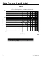
Страница 14: ...SI UNITS LD05884 Water Pressure Drop SI Units Water Flow I s 1 10 100 1000 100 10 1 Pressure Drop kPa WATER PRESSURE DROP 2 COMPRESSOR UNITS C1 C2 MODEL NUMBER YCAS COOLER 0098 0118 0138 C1 0128 0148...

Страница 15: ...L FORM 201 19 EG4 LD06103 WATER PRESSURE DROP 3 4 COMPRESSOR UNITS 1 10 100 100 1000 10000 Water Flow I s Pressure Drop kPa C3 C4 C5 MODEL NUMBER YCAS COOLER 0218 0248 0268 C3 0288 0308 0328 C4 0358 0...

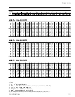
Страница 16: ...2 7 9 8 46 0 126 1 94 4 14 4 122 3 100 7 13 2 118 4 107 6 12 0 114 3 115 0 10 9 110 4 122 8 9 9 48 0 130 2 94 6 14 8 126 1 101 0 13 5 122 2 107 9 12 3 118 1 115 3 11 2 114 1 123 1 10 2 50 0 134 2 94 9...

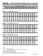
Страница 17: ...7 4 91 6 150 7 6 8 79 1 144 5 6 1 59 7 128 9 5 1 48 0 110 2 131 4 9 3 106 4 140 2 8 5 102 8 149 4 7 7 93 8 148 7 7 1 81 1 142 9 6 3 60 7 126 9 5 3 50 0 113 9 131 7 9 6 110 1 140 4 8 7 106 4 149 6 8 0...

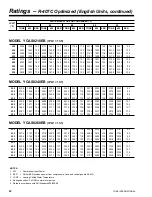
Страница 18: ...9 105 4 15 5 150 1 112 6 14 2 145 0 120 3 12 9 139 9 128 6 11 7 134 9 137 3 10 7 48 0 159 5 105 7 15 9 154 9 112 9 14 6 149 7 120 6 13 3 144 5 128 9 12 1 139 5 137 7 11 0 50 0 164 5 105 9 16 4 159 7 1...

Страница 19: ...56 5 8 8 121 1 167 0 8 0 116 9 178 0 7 3 112 6 189 0 6 6 84 2 162 6 5 7 48 0 134 6 147 0 10 0 129 8 156 8 9 1 125 3 167 2 8 3 121 0 178 2 7 5 113 8 184 6 6 9 85 5 160 1 5 9 50 0 139 1 147 3 10 3 134 2...

Страница 20: ...0 0 208 1 169 3 13 3 200 9 180 8 12 1 193 9 193 1 11 0 187 0 206 4 10 0 180 2 220 5 9 1 42 0 214 9 170 5 13 7 207 6 181 9 12 5 200 4 194 3 11 3 196 3 208 3 10 4 186 4 221 6 9 3 44 0 221 7 171 6 14 0 2...

Страница 21: ...0 8 4 165 4 243 1 7 6 159 8 258 9 6 9 144 6 256 3 6 3 109 5 223 5 5 4 48 0 183 5 214 6 9 5 177 1 228 7 8 6 171 1 243 7 7 8 165 3 259 5 7 1 147 0 251 9 6 5 111 0 220 0 5 6 50 0 189 4 215 4 9 7 183 0 22...

Страница 22: ...2 220 7 11 1 227 5 236 0 10 1 219 2 252 2 9 2 42 0 272 9 194 9 14 3 253 1 207 7 12 6 244 3 221 8 11 5 235 5 236 9 10 4 227 0 253 1 9 5 44 0 273 7 195 4 14 4 261 5 208 6 13 0 252 4 222 9 11 8 243 5 23...

Страница 23: ...2 136 5 277 0 5 3 46 0 234 2 272 1 9 2 225 9 290 3 8 4 218 0 309 6 7 6 201 1 310 7 7 0 180 6 307 7 6 4 137 6 275 0 5 3 48 0 242 1 273 0 9 5 233 6 291 2 8 6 225 6 310 3 7 9 206 5 308 2 7 2 185 7 305 8...

Страница 24: ...272 0 11 3 283 2 290 6 10 3 272 8 310 4 9 4 42 0 326 0 240 2 14 0 314 8 256 2 12 8 303 7 273 5 11 7 292 9 292 0 10 6 282 3 311 8 9 7 44 0 336 4 241 6 14 4 324 9 257 7 13 1 313 7 274 9 12 0 302 6 293 4...

Страница 25: ...67 2 338 1 5 3 46 0 290 9 335 4 9 3 280 7 357 5 8 5 270 9 381 0 7 7 261 7 405 7 7 1 224 8 382 8 6 4 168 3 335 6 5 4 48 0 300 5 336 7 9 6 290 1 358 7 8 7 280 1 382 2 8 0 269 5 404 6 7 3 227 5 375 4 6 6...

Страница 26: ...0 3 324 9 371 4 9 4 42 0 388 5 287 6 14 0 375 1 306 5 12 8 361 9 327 2 11 7 351 0 350 1 10 7 336 2 373 1 9 7 44 0 400 9 289 2 14 4 387 0 308 6 13 1 373 8 328 8 12 0 360 2 351 4 10 9 347 6 374 8 9 9 45...

Страница 27: ...85 4 496 4 6 3 213 0 434 9 5 3 46 0 376 5 435 7 9 3 363 3 464 4 8 5 350 8 494 7 7 7 338 7 527 0 7 0 287 3 491 7 6 4 214 6 431 7 5 3 48 0 388 9 437 3 9 6 375 5 465 9 8 7 362 6 496 4 8 0 348 4 524 8 7 3...

Страница 28: ...0 7 153 0 2 1 252 9 138 1 1 7 9 0 453 0 97 2 4 2 428 1 109 4 3 6 402 7 123 1 3 0 378 2 138 4 2 5 348 1 151 1 2 2 256 3 135 9 1 8 10 0 465 7 97 4 4 3 440 3 109 7 3 7 414 6 123 4 3 1 389 7 138 6 2 6 355...

Страница 29: ...20 4 154 1 2 5 393 6 173 2 2 1 347 6 183 4 1 8 7 0 526 6 108 0 4 3 494 7 121 7 3 6 466 0 137 4 3 1 433 9 154 3 2 6 406 5 173 4 2 2 352 7 180 3 1 8 8 0 541 6 108 3 4 4 509 4 122 0 3 7 477 7 137 4 3 2 4...

Страница 30: ...8 7 197 3 3 3 664 4 222 0 2 8 622 6 249 6 2 3 584 1 280 1 2 0 456 5 262 3 1 6 7 0 776 4 176 4 4 0 729 5 198 3 3 4 684 5 223 0 2 8 641 8 250 6 2 4 602 6 281 0 2 0 462 2 258 0 1 7 8 0 798 2 177 3 4 1 75...

Страница 31: ...248 6 3 4 887 3 279 9 2 8 830 4 314 9 2 4 778 8 353 2 2 0 578 5 318 6 1 6 7 0 1038 3 222 5 4 1 975 5 249 7 3 4 914 4 281 0 2 9 856 4 315 9 2 5 803 9 354 1 2 1 585 8 313 8 1 7 8 0 1067 6 223 5 4 2 100...

Страница 32: ...51 1 2 4 883 0 393 8 2 0 696 2 373 4 1 7 7 0 1177 7 248 3 4 1 1105 7 278 9 3 5 1036 7 313 5 2 9 970 9 352 2 2 5 911 0 394 8 2 1 705 0 367 4 1 7 8 0 1210 8 249 4 4 2 1137 5 280 1 3 6 1067 5 314 7 3 0 1...

Страница 33: ...4 1142 8 511 6 2 0 888 9 479 7 1 7 7 0 1524 2 322 4 4 1 1431 2 362 1 3 5 1341 8 407 1 2 9 1256 6 457 6 2 5 1179 2 512 9 2 1 900 3 472 0 1 7 8 0 1567 0 324 0 4 2 1472 4 363 7 3 6 1381 7 408 7 3 0 1295...

Страница 34: ...2 1 8 2 1 8 2 1 8 2 1 8 Fan Motor Speed revs min 1140 0 1140 0 1140 0 1140 0 1140 0 1140 0 1140 0 1140 0 1140 0 Fan Diameter inches 35 4 35 4 35 4 35 4 35 4 35 4 35 4 35 4 35 4 Fan Tip Speed ft min 10...

Страница 35: ...4 4 4 4 5 5 4 5 5 6 4 4 4 4 5 5 4 4 5 5 4 4 3 2 8 3 2 8 3 2 8 3 2 8 3 2 8 3 2 8 3 2 8 3 2 8 3 2 8 1140 1140 1140 1140 1140 1140 1140 1140 1140 35 4 35 4 35 4 35 4 35 4 35 4 35 4 35 4 35 4 10 575 10 57...

Страница 36: ...andard Fans Fan Motor HP kW 2 1 8 2 1 8 2 1 8 2 1 8 2 1 8 2 1 8 2 1 8 2 1 8 2 1 8 Fan Motor Speed revs sec 19 0 19 0 19 0 19 0 19 0 19 0 19 0 19 0 19 0 Fan Diameter mm 900 900 900 900 900 900 900 900...

Страница 37: ...47 6 53 5 53 5 3 3 3 3 3 3 3 3 3 512 512 512 512 512 512 512 512 512 4 4 4 4 4 4 4 4 4 4 4 4 5 5 4 5 5 6 4 4 4 4 5 5 4 4 5 5 4 4 3 2 8 3 2 8 3 2 8 3 2 8 3 2 8 3 2 8 3 2 8 3 2 8 3 2 8 19 19 19 19 19 19...

Страница 38: ...possible diminished performance YORK s unit controls will optimize operation without nuisance high pressure safety cutout however the system designer must consider potential performance degradation A...

Страница 39: ...YORK INTERNATIONAL FORM 201 19 EG4 LD05184 LD05163 CENTER OF GRAVITY Alum YCAS X Y Z 0098 77 5 44 9 38 8 0118 76 9 45 0 38 3 CENTER OF GRAVITY Copper YCAS X Y Z 0098 77 4 44 8 41 0 0118 77 3 45 0 38...

Страница 40: ...unpredictable air flow patterns and possible diminished performance YORK s unit controls will optimize operation without nuisance high pressure safety cutout however the system designer must consider...

Страница 41: ...5 3 7 8 CONT ROL P A NE L F OR SY S 1 P OWE R E L E MENT S F OR SY S 2 P OWER E L E MENT S ORI GI N VI E W D D MOUNT I NG 5 8 DI A HOL E S T YP A B C D E F G H LD05639 LD05640 CENTER OF GRAVITY Coppe...

Страница 42: ...s and possible diminished performance YORK s unit controls will optimize operation without nuisance high pressure safety cutout however the system designer must consider potential performance degradat...

Страница 43: ...43 YORK INTERNATIONAL FORM 201 19 EG4 LD05643 LD05644 CENTER OF GRAVITY Copper YCAS X Y Z 0138 105 9 45 1 40 2 CENTER OF GRAVITY Alum YCAS X Y Z 0138 104 1 45 2 38 8...

Страница 44: ...possible diminished performance YORK s unit controls will optimize operation without nuisance high pressure safety cutout however the system designer must consider potential performance degradation A...

Страница 45: ...M 201 19 EG4 LD05647 LD05648 CENTER OF GRAVITY Copper YCAS X Y Z 0148 108 0 42 9 38 1 0158 107 8 42 9 38 0 0178 108 0 43 0 38 0 CENTER OF GRAVITY Alum YCAS X Y Z 0148 106 6 42 8 36 6 0158 106 3 42 8 3...

Страница 46: ...possible diminished performance YORK s unit controls will optimize operation without nuisance high pressure safety cutout however the system designer must consider potential performance degradation A...

Страница 47: ...ORK INTERNATIONAL FORM 201 19 EG4 LD05664 CENTER OF GRAVITY Alum YCAS X Y Z 0198 132 9 43 2 38 4 0208 133 1 43 3 38 1 CENTER OF GRAVITY Copper YCAS X Y Z 0198 134 2 43 3 39 8 0208 134 3 43 4 39 5 LD05...

Страница 48: ...or air recirculation ensures rated performance reli able operation and ease of maintenance Site restrictions may compromise minimum clearances indicated below resulting in unpredictable air flow patt...

Страница 49: ...149 5 8 VIEW D D HOLES TYP MOUNTING 5 8 DIA CONTROL PANEL FOR SYS 2 POWER ELEMENTS FOR SYS 1 3 POWER ELEMENTS WATER OUTLET WATER INLET POWER OPENING DISTRIBUTION ORIGIN HOLES EACH SIDE 4 2 1 4 DIA RIG...

Страница 50: ...ir recirculation ensures rated performance reli able operation and ease of maintenance Site restrictions may compromise minimum clearances indicated below resulting in unpredictable air flow patterns...

Страница 51: ...1 4 1 1 4 X Z G C 68 36 78 89 11 16 342 1 4 142 157 3 16 VIEW D D HOLES TYP MOUNTING 5 8 DIA CONTROL PANEL FOR SYS 2 POWER ELEMENTS FOR SYS 1 3 POWER ELEMENTS WATER OUTLET WATER INLET POWER OPENING D...

Страница 52: ...ir recirculation ensures rated performance reli able operation and ease of maintenance Site restrictions may compromise minimum clearances indicated below resulting in unpredictable air flow patterns...

Страница 53: ...30 30 1 1 4 1 1 4 68 36 390 1 4 115 7 16 89 11 16 88 WATER INLET WATER OUTLET HOLES EACH SIDE 4 2 1 4 DIA RIGGING POWER OPENING 5 8 DIA MOUNTING HOLES TYP POWER OPENING VIEW D D POWER ELEMENTS FOR SY...

Страница 54: ...res rated performance reli able operation and ease of maintenance Site restrictions may compromise minimum clearances indicated below resulting in unpredictable air flow patterns and possible diminish...

Страница 55: ...6 78 10 10 438 1 4 115 7 16 89 11 16 142 157 3 16 88 HOLES TYP 5 8 DIA MOUNTING CONTROL PANEL VIEW D D POWER ELEMENTS FOR SYS 1 3 FOR SYS 2 POWER ELEMENTS SYS 3 SYS 1 2 APPROX OPERATING WEIGHT DISTRIB...

Страница 56: ...res rated performance reli able operation and ease of maintenance Site restrictions may compromise minimum clearances indicated below resulting in unpredictable air flow patterns and possible diminish...

Страница 57: ...A A 30 30 88 1 1 4 1 1 4 X Z G C 75 1 2 36 78 89 11 16 10 10 438 1 4 142 264 9 16 5 8 DIA MOUNTING HOLES TYP VIEW D D CONTROL PANEL POWER ELEMENTS FOR SYS 1 3 POWER ELEMENTS FOR SYS 2 4 POWER OPENING...

Страница 58: ...ensures rated performance reli able operation and ease of maintenance Site restrictions may compromise minimum clearances indicated below resulting in unpredictable air flow patterns and possible dim...

Страница 59: ...16 31 3 4 J D D 2 96 7 1 2 A A 30 30 1 1 4 1 1 4 36 78 88 WATER OUTLET WATER INLET POWER OPENING 4 2 1 4 DIA RIGGING HOLES EACH SIDE CONTROL PANEL POWER ELEMENTS FOR SYS 2 4 FOR SYS 1 3 POWER ELEMENT...

Страница 60: ...nit controls will optimize operation without nuisance high pressure safety cutout however the system designer must consider potential performance degradation Access to the unit control center assumes...

Страница 61: ...1 YORK INTERNATIONAL FORM 201 19 EG4 LD05828 LD05829 CENTER OF GRAVITY Alum YCAS X Y Z 0098 1967 1141 985 0118 1953 1142 972 CENTER OF GRAVITY Copper YCAS X Y Z 0098 1965 1139 1040 0118 1962 1140 1027...

Страница 62: ...K s unit controls will optimize operation without nuisance high pressure safety cutout however the system designer must consider potential performance degradation Access to the unit control center ass...

Страница 63: ...63 YORK INTERNATIONAL FORM 201 19 EG4 LD05832 LD05833 CENTER OF GRAVITY Copper YCAS X Y Z 0128 2728 1086 980 CENTER OF GRAVITY Alum YCAS X Y Z 0128 2690 1083 943...

Страница 64: ...RK s unit controls will optimize operation without nuisance high pressure safety cutout however the system designer must consider potential performance degradation Access to the unit control center as...

Страница 65: ...65 YORK INTERNATIONAL FORM 201 19 EG4 LD05836 LD05837 CENTER OF GRAVITY Copper YCAS X Y Z 0138 2689 1146 1021 CENTER OF GRAVITY Alum YCAS X Y Z 0138 2645 1148 987...

Страница 66: ...nit controls will optimize operation without nuisance high pressure safety cutout however the system designer must consider potential performance degradation Access to the unit control center assumes...

Страница 67: ...AL FORM 201 19 EG4 LD05840 LD05841 CENTER OF GRAVITY Copper YCAS X Y Z 0148 2742 1090 967 0158 2737 1090 965 0178 2742 1093 965 CENTER OF GRAVITY Alum YCAS X Y Z 0148 2706 1087 930 0158 2701 1087 928...

Страница 68: ...nit controls will optimize operation without nuisance high pressure safety cutout however the system designer must consider potential performance degradation Access to the unit control center assumes...

Страница 69: ...9 YORK INTERNATIONAL FORM 201 19 EG4 LD05844 LD05845 CENTER OF GRAVITY Alum YCAS X Y Z 0198 3376 1098 975 0208 3380 1100 967 CENTER OF GRAVITY Copper YCAS X Y Z 0198 3408 1100 1012 0208 3411 1102 1004...

Страница 70: ...ce degradation Access to the unit control center assumes the unit is no higher than on spring isolators Recommended minimum clearances Side to wall 2m rear to wall 2m control panel end to wall 1 2m to...

Страница 71: ...1 2277 8694 3251 3800 VIEW D D HOLES TYP MOUNTING 16 DIA CONTROL PANEL FOR SYS 2 POWER ELEMENTS FOR SYS 1 3 POWER ELEMENTS WATER OUTLET WATER INLET POWER OPENING ORIGIN HOLES EACH SIDE 4 57 DIA RIGGIN...

Страница 72: ...rmance degradation Access to the unit control center assumes the unit is no higher than on spring isolators Recommended minimum clearances Side to wall 2m rear to wall 2m control panel end to wall 1 2...

Страница 73: ...62 762 2235 32 32 X Z G C 1727 914 1981 2277 8694 3607 3992 VIEW D D HOLES TYP MOUNTING 16 DIA CONTROL PANEL FOR SYS 2 POWER ELEMENTS FOR SYS 1 3 POWER ELEMENTS WATER OUTLET WATER INLET POWER OPENING...

Страница 74: ...ormance degradation Access to the unit control center assumes the unit is no higher than on spring isolators Recommended minimum clearances Side to wall 2m rear to wall 2m control panel end to wall 1...

Страница 75: ...614 2438 A A 762 762 32 32 1727 914 9913 2933 2277 2235 WATER INLET WATER OUTLET HOLES EACH SIDE 4 57 DIA RIGGING POWER OPENING 16 DIA MOUNTING HOLES TYP POWER OPENING VIEW D D POWER ELEMENTS FOR SYS...

Страница 76: ...rmance degradation Access to the unit control center assumes the unit is no higher than on spring isolators Recommended minimum clearances Side to wall 2m rear to wall 2m control panel end to wall 1 2...

Страница 77: ...G C 1727 914 1981 10 10 11132 2933 2277 3607 3992 2235 HOLES TYP 16 DIA MOUNTING CONTROL PANEL VIEW D D POWER ELEMENTS FOR SYS 1 3 FOR SYS 2 POWER ELEMENTS SYS 3 SYS 1 2 POWER OPENING ORIGIN HOLES EAC...

Страница 78: ...rmance degradation Access to the unit control center assumes the unit is no higher than on spring isolators Recommended minimum clearances Side to wall 2m rear to wall 2m control panel end to wall 1 2...

Страница 79: ...A A 762 762 2235 32 32 X Z G C 1918 914 1981 2277 10 10 11132 3607 6720 16 DIA MOUNTING HOLES TYP VIEW D D CONTROL PANEL POWER ELEMENTS FOR SYS 1 3 POWER ELEMENTS FOR SYS 2 4 POWER OPENING ORIGIN HOLE...

Страница 80: ...e degradation Access to the unit control center assumes the unit is no higher than on spring isolators Recommended minimum clearances Side to wall 2m rear to wall 2m control panel end to wall 1 2m top...

Страница 81: ...06 J D D 51 2438 191 A A 762 762 32 32 914 1981 2235 WATER OUTLET WATER INLET POWER OPENING 4 57 DIA RIGGING HOLES EACH SIDE CONTROL PANEL POWER ELEMENTS FOR SYS 2 4 FOR SYS 1 3 POWER ELEMENTS 16 DIA...

Страница 82: ...N BY MODEL lbs 60 Hz A B C D E F G H I J K L M N O P Total YCAS0098 2 070 1 640 1 211 1 986 1 573 1 161 9 641 YCAS0118 2 173 1 701 1 230 2 078 1 627 1 176 9 985 YCAS0128 1 798 1 643 1 488 1 334 1 914...

Страница 83: ...1 2 28 2 31 2 27 2 32 2 27 2 26 2 32 ALUMINUM FINS SEISMIC ISOLATOR SELECTIONS VMC MODEL AWMR X XXX See Table 2 60 Hz A B C D E F G H I J K L M N O P YCAS0098 1 553 1 551 1 531 1 553 1 551 1 531 YCAS0...

Страница 84: ...RED 4 RED 4 RED YCAS0218 4 RED 4 RED 4 RED 4 BLK 4 BLK 4 BLK 4 RED 4 RED 4 GRN 4 RED 4 RED 4 RED YCAS0248 4 RED 4 RED 4 RED 4 BLK 4 BLK 4 BLK 4 RED 4 RED 4 GRN 4 RED 4 RED 4 RED YCAS0268 4 RED 4 RED 4...

Страница 85: ...2 486 1 513 1 395 2 667 2 083 1 870 1 666 1 548 2 654 1 345 1 395 2 667 30 606 YCAS0398 2 066 1 918 2 162 1 467 2 693 1 636 1 371 2 750 2 184 1 935 2 184 1 472 2 693 1 636 1 371 2 750 32 286 YCAS0418...

Страница 86: ...2 53 1 551 2 532 2 521 1 532 2 532 YCAS0398 1 553 1 553 2 530 1 532 2 532 2 53 2 521 2 532 1 553 1 553 2 530 1 532 2 532 2 53 2 521 2 532 YCAS0418 1 553 1 553 2 530 1 532 2 532 2 53 2 521 2 532 1 553...

Страница 87: ...ED 4 RED 4 RED 4 RED YCAS0218 4 RED 4 RED 4 RED 4 BLK 4 RED 4 BLK 4 RED 4 RED 4 GRN 4 RED 4 GRN 4 RED YCAS0248 4 RED 4 RED 4 GRN 4 RED 4 RED 4 BLK 4 RED 4 RED 4 GRN 4 RED 4 GRN 4 RED YCAS0268 4 RED 4...

Страница 88: ...86 1 728 2 834 1 465 1 545 2 937 33 135 YCAS0398 2 229 2 081 2 325 1 630 2 855 1 798 1 568 2 998 2 239 2 098 2 347 1 635 2 855 1 798 1 568 2 998 35 025 YCAS0418 2 230 2 083 2 376 1 642 2 857 1 800 1 5...

Страница 89: ...2 28 2 35 2 32 2 31 2 32 2 28 2 35 2 28 2 28 2 35 CP 4 XX COPPER FINS WITH OPTIONAL SILENCER KIT SEISMIC ISOLATOR SELECTIONS VMC MODEL AWMR X XXX See Table 2 60 Hz A B C D E F G H I J K L M N O P YCA...

Страница 90: ...D 4 RED 4 GRN 4 RED 4 RED 4 GRN 4 GRN YCAS0218 4 RED 4 GRN 4 GRN 4 RED 4 RED 4 RED 4 RED 4 GRN 4 GRN 4 RED 4 GRN 4 RED YCAS0248 4 RED 4 GRN 4 GRN 4 RED 4 RED 4 RED 4 RED 4 GRN 4 GRN 4 RED 4 GRN 4 RED...

Страница 91: ...91 YORK INTERNATIONAL FORM 201 19 EG4 This page intentionally left blank...

Страница 92: ...B C D E R 3 or RD 3 5 5 3 375 1 75 2 875 2 5 0 5 4 125 0 563 0 25 139 7 85 8 44 4 73 2 63 5 12 7 104 8 14 4 6 3 R 4 or RD 4 6 25 4 625 1 625 2 75 3 0 0 5 5 0 0 563 0 375 158 7 117 6 41 4 69 8 76 2 12...

Страница 93: ...00 408 2 1 22 30 7 Red CP 2 27 1500 680 4 1 06 26 9 Orange CP 2 28 1800 816 4 1 02 25 9 Green CP 2 31 2200 997 9 0 83 21 0 Gray CP 2 32 2600 1179 3 0 74 18 7 White TABLE 3 1 SPRING ISOLATORS 1 ISOLATO...

Страница 94: ...0 142 150 175 225 2 4 0 4 300 4 300 101 228 719 4 4 0 19 0 575 113 150 150 175 6 1 0 4 300 4 300 81 182 574 4 3 1 15 2 200 324 400 400 500 2 0 500 2 3 0 250 2 3 0 250 233 591 1866 4 8 2 33 0 230 284 4...

Страница 95: ...324 400 400 500 2 0 500 2 3 0 250 2 3 0 250 233 591 1866 4 8 2 33 0 230 284 400 350 450 2 0 500 2 3 0 250 2 3 0 250 203 481 1518 4 7 8 38 0 0148EB 380 172 200 225 250 2 4 0 4 300 4 300 122 285 900 4...

Страница 96: ...80 485 600 600 600 2 1 0 300 2 250 500 212 343 1093 166 343 1093 8 5 1 21 0 0288EB 460 410 600 450 500 2 0 500 2 250 500 176 280 893 137 280 893 8 5 2 29 0 575 325 400 400 400 2 0 500 2 3 0 250 141 22...

Страница 97: ...09 224 714 4 3 9 25 9 380 264 400 350 450 2 0 500 2 3 0 250 195 343 1093 5 5 1 21 0 0308EB 460 222 250 300 350 1 0 300 4 300 161 280 893 5 5 2 29 0 575 177 200 225 300 2 4 0 6 350 129 224 714 5 3 9 25...

Страница 98: ...0 300 300 1 0 300 6 350 575 182 200 225 250 1 0 300 6 350 200 589 800 700 800 2 2 0 500 3 2 0 400 230 517 600 600 700 2 2 0 500 2 250 500 0138EB 380 313 400 350 400 2 0 500 2 3 0 250 460 259 400 300 3...

Страница 99: ...4 4 0 19 0 575 81 182 574 4 3 1 15 2 81 182 574 4 3 1 15 2 200 233 591 1866 4 8 2 33 0 233 591 1866 4 8 2 33 0 230 203 481 1518 4 7 8 38 0 203 481 1518 4 7 8 38 0 0148EB 380 122 285 900 4 4 8 23 0 12...

Страница 100: ...1 800 800 1000 2 2 0 500 3 2 0 400 212 343 1093 166 343 1093 8 5 1 21 0 0288EB 460 568 600 700 800 2 2 0 500 2 250 500 176 280 893 137 280 893 8 5 2 29 0 575 450 600 500 600 2 1 0 300 2 250 500 141 22...

Страница 101: ...9 25 9 380 689 800 800 1000 3 1 0 300 3 2 0 400 195 343 1093 5 5 1 21 0 0308EB 460 584 800 700 800 2 2 0 500 3 2 0 400 161 280 893 5 5 2 29 0 575 462 600 500 600 2 1 0 300 2 250 500 129 224 714 5 3 9...

Страница 102: ...400 350 400 2 0 500 2 3 0 250 0118EB 460 236 250 300 350 1 0 300 6 350 575 189 200 225 250 1 0 300 6 350 380 275 400 350 350 2 0 500 2 3 0 250 0128EB 460 228 250 300 300 1 0 300 6 350 575 182 200 225...

Страница 103: ...4 8 23 0 122 900 4 4 8 23 0 0138EB 460 101 719 4 4 0 19 0 101 719 4 4 0 19 0 575 81 574 4 3 1 15 2 81 574 4 3 1 15 2 380 122 900 4 4 8 23 0 122 900 4 4 8 23 0 0148EB 460 101 719 4 4 0 19 0 101 719 4 4...

Страница 104: ...101 719 4 4 0 19 0 69 542 4 4 0 19 0 575 182 250 6 350 81 574 4 3 1 15 2 56 431 4 3 1 15 2 380 313 400 2 3 0 250 122 900 4 4 8 23 0 122 900 4 4 8 23 0 0138EB 460 259 400 2 3 0 250 101 719 4 4 0 19 0 1...

Страница 105: ...50 maximum plus 100 of rated load amps included in the circuit Minimum circuit breaker rating 1 5 x largest compressor RLA other compressor RLAs fans x each fan motor FLA 6 Maximum circuit breaker is...

Страница 106: ...106 YORK INTERNATIONAL Power Connection Options FIG 1 MULTIPLE POINT POWER SUPPLY CONNECTION STANDARD UNIT FIG 2 OPTIONAL SINGLE POINT POWER SUPPLY CONNECTION WITH INDIVIDUAL SYSTEM CIRCUIT BREAKERS...

Страница 107: ...RCUIT BREAKER NOTES 1 Dashed Line indicates Field Provided Wiring 2 The above recommendations are based on the National Electric Code and using copper connectors only Field wiring must also comply wit...

Страница 108: ...inued 3 4 COMPRESSOR POWER CONNECTION OPTIONS FIG 5 MULTIPLE POINT POWER SUPPLY CONNECTION LD05552 FIG 6 MULTIPLE POINT POWER SUPPLY CONNECTION WITH INDIVIDUAL SYSTEM CIRCUIT BREAKERS LD05553 See page...

Страница 109: ...Field wiring must also comply with local codes Group Rated breaker must be HACR type for cU L machines LEGEND Transient Voltage Suppression Terminal Block for Customer Connections Terminal Block for...

Страница 110: ...110 YORK INTERNATIONAL Typical Control Wiring 2 Compressor...

Страница 111: ...ll not be run in the same conduit with any line voltage wiring 3 To cycle unit on and off automatically with contact shown install a cycling device in series with the flow switch flsw See note 2 for c...

Страница 112: ...ators to minimize transmission of vibration into the building structure Additional support should be provided to the roof at the isolator locations Ground Locations Units must be installed on a sub st...

Страница 113: ...s defined by ANSI ASHRAE STAN DARD 34 Number Designation and Safety Classi fication of Refrigerants Chiller shall include but is not limited to a complete system with not less than two independent ref...

Страница 114: ...Heat Exchangers to increase overall unit efficiency U L cU L Listed 450 PSIG 31 Bar design working pressure 2 05 CONTROLS A General Automatic start stop operating and pro tection sequences across the...

Страница 115: ...safer servicing Provide main power connection s compressor and fan motor start contactors current overloads and factory wiring 2 Field power supply wiring connections shall be to a single power cente...

Страница 116: ...f standard 3 4 2 Provide DX Cooler with 300 PSIG water side design working pressure in lieu of standard 150 PSIG 3 Provide Raised Face Flanges for cooler nozzles a 150 PSIG welded flanges field kit ma...

Страница 117: ...ructions Adjust and level chiller on support structure C Components Installing Contractor shall provide and install all auxiliary devices and accessories for fully operational chiller D Electrical Coo...

Страница 118: ...118 YORK INTERNATIONAL This page intentionally left blank...

Страница 119: ...119 YORK INTERNATIONAL FORM 201 19 EG4 This page intentionally left blank...

Страница 120: ...nnsylvania USA 17405 1592 Subject to change without notice Printed in USA Copyright by York International Corporation 2001 ALL RIGHTS RESERVED Form 201 19 EG4 903 Supersedes 2018 18 EG4 301 Tele 800 8...

Отзывы: