background image

5132210-UIM-H-0916

14

Johnson Controls Unitary Products

SECTION VI: OPERATION

The unit is controlled by a conventional heating/cooling thermostat. If an
electronic thermostat is used, make sure it has a common connection.
DO NOT use a power stealing thermostat.

COOLING SEQUENCE OF OPERATIONS

When the thermostat calls for COOL, the thermostat terminals G and Y
are energized, which signals the compressor, outdoor fan and indoor
blower to run.

With a call for Y, the circulating fan is energized at cooling speed.

When the thermostat is satisfied, terminals G and Y are de-energized,
de-energizing the compressor and outdoor fan.

After a cool fan off delay timing of 30 seconds, the circulating fan is de-
energized.

Safety Controls

The control circuit includes the following safety controls:

High Pressure Switch (HP) - This switch protects against excessive dis-
charge pressures due to a blocked condenser coil or a condenser
motor failure (opens at 650 ± 25 psig and closes at 450 ± 25 psig).

The above pressure switches are specifically designed to operate with
R-410A systems. R-22 pressure switches must not be used as replace-
ments for the R-410A pressure switches.

Circulating Fan

When the thermostat calls for FAN, the thermostat terminal G is ener-
gized signaling the circulating fan to run at the G-Speed airflow.

If a call for COOL occurs (Y), the circulating fan switches to run at the Y-
Speed airflow.

If a call for HEAT occurs (W), the circulating fan switches to W-Speed
after a 30 second delay.

When the thermostat ends the call for FAN, the thermostat terminal G is
de-energized, de-energizing the circulating fan.

HEATING SEQUENCE OF OPERATIONS

This dual fuel package unit has two stages of heat. Primary heating is
accomplished by the heat pump section. Secondary heating, supple-
mental heating and back up heating is accomplished by the gas heating
section. The gas heating section is also used to temper the indoor dis-
charge air during heat pump defrost operation. The system is not
designed to run heat pump heating and gas heating at the same time.
However, the unit functions this way if the incorrect indoor thermostat is
used or if the incorrect indoor thermostat settings are selected. If the
heat pump and gas heating sections are run at the same time, HI LIMIT
trips may occur. A “Y” call without an “O” call from the indoor thermostat
is primary (heat pump) heat. A “W” call from the indoor thermostat is
secondary or emergency (gas) heat. The indoor thermostat MUST lock
out the heat pump section on a call for supplemental heat or emergency
heat.

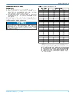
Table 14: 

Additional Static Resistance

Size (Tons)

CFM

Wet Indoor Coil

Economizer

1

1. The pressure drop through the economizer is greater for 100% outdoor air 

than for 100% return air. If the resistance of the return air duct is less than 
0.25 IWG, the unit will deliver less CFM during full economizer operation.

2. Filter pressure drop based on standard filter media tested at velocities not 

to exceed 300 ft/min.

Filter/Frame Kit

24 (2.0)

500

0.01

0.00

0.01

600

0.01

0.00

0.02

700

0.01

0.00

0.04

800

0.02

0.01

0.06

900

0.03

0.01

0.08

1000

0.04

0.01

0.10

1100

0.05

0.01

0.13

1200

0.06

0.02

0.16

30 (2.5)

700

0.01

0.00

0.04

800

0.02

0.01

0.06

900

0.03

0.01

0.08

1000

0.04

0.01

0.10

1100

0.05

0.01

0.13

1200

0.06

0.02

0.16

1300

0.07

0.03

0.17

36 (3.0)

700

0.01

0.00

0.04

800

0.02

0.01

0.06

900

0.03

0.01

0.08

1000

0.04

0.01

0.10

1100

0.05

0.01

0.13

1200

0.06

0.02

0.16

1300

0.07

0.03

0.17

1400

0.08

0.04

0.18

42 (3.5)

1100

0.02

0.02

0.04

1200

0.03

0.02

0.04

1300

0.04

0.02

0.05

1400

0.05

0.03

0.05

1500

0.06

0.04

0.06

1600

0.07

0.04

0.07

1700

0.07

0.04

0.08

1800

0.08

0.04

0.09

1900

0.09

0.05

0.10

2000

0.09

0.05

0.11

48 (4.0)

1100

0.02

0.02

0.04

1200

0.03

0.02

0.04

1300

0.04

0.02

0.05

1400

0.05

0.03

0.05

1500

0.06

0.04

0.06

1600

0.07

0.04

0.07

1700

0.07

0.04

0.08

1800

0.08

0.04

0.09

1900

0.09

0.05

0.10

2000

0.09

0.05

0.11

60 (5.0)

1100

0.02

0.02

0.04

1200

0.03

0.02

0.04

1300

0.04

0.02

0.05

1400

0.05

0.03

0.05

1500

0.06

0.04

0.06

1600

0.07

0.04

0.07

1700

0.07

0.04

0.08

1800

0.08

0.04

0.09

1900

0.09

0.05

0.10

2000

0.09

0.05

0.11

NOTICE

This unit REQUIRES the use of a thermostat to control fossil fuel
(dual fuel) operation.

 WARNING

The ability to properly perform maintenance on this equipment
requires certain expertise, mechanical skills, tools and equipment. If
you do not possess these, do not attempt to perform any mainte-
nance other than those procedures recommended in this Installation
Manual. Failure to heed this warning could result in serious injury
and possible damage to this equipment.

!

Содержание PHG4 Series

Страница 1: ...or installation Only gas piping electric power and duct connections are required at the point of installation The gas fired heaters have spark ignition The refrigerant system is fully charged with R 4...

Страница 2: ...mproper installation adjustment alteration service or mainte nance can cause injury or property damage Refer to this manual For assistance or additional information consult a qualified installer servi...

Страница 3: ...o a unit to meet local codes they are to be installed at the dealer s and or customer s expense Size of unit for proposed installation should be based on heat loss heat gain calculation made according...

Страница 4: ...are provided for this purpose WARNING Do not attach supply and return duct work to the bottom of the unit base pan as the drain pan could be compromised WARNING Excessive exposure of this furnace to...

Страница 5: ...ection Distance in Direction Distance in Top3 3 Units must be installed outdoors Over hanging structure or shrubs should not obstruct condenser air discharge outlet 36 Power Entry Right Side 36 Side O...

Страница 6: ...n the return air ductwork or install a Filter Frame Kit A filter rack and high velocity filters are standard on three phase units Filters must always be used and must be kept clean When filters become...

Страница 7: ...rate branch circuit fed directly from the main distribution panel and properly fused Refer to Figures 7 and 8 for typical field wiring and to the appropriate unit wiring diagram for control circuit an...

Страница 8: ...51 1 4 Width 35 3 4 35 3 4 45 3 4 45 3 4 45 3 4 45 3 4 Height 47 49 49 49 53 55 Operating WT lbs 394 404 449 453 498 505 532 534 551 559 564 577 581 588 Compressors Type Scroll Scroll Scroll Scroll Sc...

Страница 9: ...5 The gas supply should be a separate line and installed in accor dance with all applicable safety codes After the gas connections have been completed open the main shut off valve admitting nor mal ga...

Страница 10: ...leaks to check all connections A fire or explosion may result causing property damage personal injury or loss of life Table 9 High Altitude Gas Orifice Sizing ELEVATION ABOVE SEA LEVEL FEET GAS TYPE...

Страница 11: ...864 780 Medium High 4 1349 1297 1265 1224 1185 1146 1107 1063 975 High 5 1487 1462 1392 1331 1318 1281 1241 1201 1121 30050 Low 1 700 657 599 554 512 461 411 365 273 Low Medium 2 906 868 825 779 735...

Страница 12: ...1858 1807 1749 1710 1667 1629 1589 1546 1460 Medium 3 2054 1998 1934 1890 1843 1801 1757 1710 1616 Medium High 4 2195 2144 2098 2049 2003 1955 1883 1868 1838 High 5 2445 2388 2306 2293 2235 2178 2129...

Страница 13: ...w 1 1032 999 970 938 910 879 843 808 737 Low Medium 2 1272 1236 1204 1165 1129 1081 1037 968 829 Medium 3 1611 1574 1518 1494 1439 1405 1357 1266 1083 Medium High 4 1892 1777 1771 1701 1639 1617 1565...

Страница 14: ...ings are selected If the heat pump and gas heating sections are run at the same time HI LIMIT trips may occur A Y call without an O call from the indoor thermostat is primary heat pump heat A W call f...

Страница 15: ...frost cycle is initiated A temperature inhibit feature prohibits defrost if the coil temperature is above 40 F A forced defrost feature puts the system into a defrost period every 6 hours and 4 minute...

Страница 16: ...g 8 on the LED Post Purge The control board runs the induced draft motor for a 15 second post purge period and then de energizes the inducer If a call for heat occurs during post purge the control fin...

Страница 17: ...hich automatically lights the burners 5 Remove the access panel 6 Turn the gas valve switch to the OFF position 7 Wait five 5 minutes to clear out any gas If you then smell gas STOP Follow B in the in...

Страница 18: ...within the range shown on the rating plate and the data in Table 6 After the temperature rise has been determined the CFM can be calcu lated as follows Direct Drive Blower All units have direct drive...

Страница 19: ...as in your particular locality Contact your gas company for this information since it varies widely from city to city Table 19 Gas Rate Cubic Feet Per Hour1 Seconds for9 One Rev Size of Test Dial 1 2...

Страница 20: ...VOLTAGE 19 2 VAC PREVENTING FURTHER RELAY OUTPUTS FOR 2 SECONDS LOW VOLTAGE 16 VAC STOPPED CURRENT RELAY OUTPUTS FOR 2 SECONDS LIQUID LINE SENSOR FAILURE OPEN OR SHORTED OUTDOOR AMBIENT SENSOR FAILUR...

Страница 21: ...EVENTING FURTHER RELAY OUTPUTS FOR 2 SECONDS LOW VOLTAGE 16 VAC STOPPED CURRENT RELAY OUTPUTS FOR 2 SECONDS LIQUID LINE SENSOR FAILURE OPEN OR SHORTED OUTDOOR AMBIENT SENSOR FAILURE OPEN OR SHORTED CO...

Страница 22: ...Manifold sets must be at least 700 psig high side and 180 psig low side with 550 psig retard All hoses must have a service pressure rating of 800 psig Leak detectors must be designed to detect HFC re...

Страница 23: ...le timer Measured voltage L1 to L2 L2 to L3 L1 to L3 Total amperes L1 L2 L3 Compressor amperes L1 L2 L3 Measured voltage R and C outdoor unit control board Electrical Connections Inspection Check all...

Страница 24: ...U H Measured BTU H Clock Gas Meter Nat Gas Supply Air Dry Bulb Temp Temp Rise Return Air Dry Bulb Temp Manifold Pressure at 100 Firing Rate w c Inlet Gas Pressure w c LP Gas Conversion Kit LP Conversi...

Отзывы: