background image

31

FORM 160.47-NOM3

YORK INTERNATIONAL

OIL SYSTEM (CONT’D)

The oil pressure transducer is located at the SB-2 mani-
fold.  The differential  pressure is measured as the dif-
ference between the Oil Pressure Transducer at SB-2
and the Filter Pressure Transducer located in the oil
separator.  This value is compared to the limits in the
control panel logic.  If the oil filter differential reaches
20 psid, a warning message is displayed by the control
panel display.  If the oil filter reaches 25 psid, a safety
shutdown is initiated. See Figure 18.

An oil supply line from the manifold at SB-2 is piped to
the capacity control directional valve at Port P.  The 4-
way capacity control solenoid (directional) valve directs
oil pressure against one side or the other of the slide
valve piston. The opposite side of the slide valve is re-
lieved to suction pressure at compressor port SC-11.
The differential pressure between the P port and the
suction pressure at Compressor Port SC-11 is what pro-
vides the force to load or unload the slide valve and
provide capacity control.  Refer to the Capacity Control
Schematic Diagram.

Oil flows from the oil manifold at SB-2 to the brazed
plate, refrigerant cooled oil cooler. Cool oil leaving the
brazed plate heat exchanger flows to the eductor block
manifold. A new oil circuit has been incorporated into
the oil eductor block in Design Level “D”. The oil cir-
cuit is separate from the eductor oil management sys-
tem. See Figure 19.

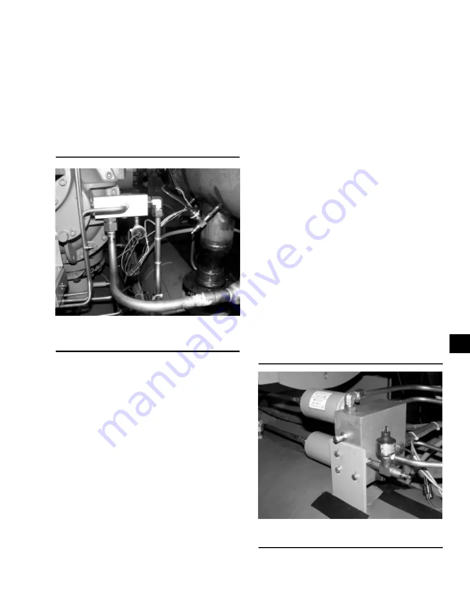
The eductor block manifold oil circuit contains the Seal
Oil Pressure Transducer and a High Oil Temperature

00091VIP

FIG. 18 – OIL PRESSURE  TRANSDUCER

LOCATION

00092VIP

FIG. 19 –  EDUCTOR BLOCK

Safety sensor. The Seal Oil Pressure is monitored by
the control panel. The differential pressure between the
Seal Oil Pressure and the Evaporator Pressure Trans-
ducer is calculated and compared to the control panel
logic. If the differential reaches the set point (30 psid
for R-22 and 20 psid for R-134a, the control panel will
initiate a safety shutdown.  A high oil temperature safety
shutdown will be initiated at 170ºF (77ºC).

The oil leaving the oil eductor manifold block flows into
the compressor at compressor port SB-3 to lubricate
the compressor bearings and shaft seal. All of the oil
that is injected into the compressor mixes with refriger-
ant gas during compression. The oil and refrigerant gas
is discharged into the oil separator, where it is sepa-
rated and returned to the oil sump. A high discharge
temperature safety is located in the discharge line, be-
tween the compressor and oil separator. This safety will
initiate a safety shutdown at 210ºF (99ºC).

Oil is separated from the refrigerant gas in the oil sepa-
rator. Oil is separated from the refrigerant gas in a three
step process.

In the first stage of oil separation, high velocity oil and
refrigerant gas in the compressor discharge line under
goes a rapid reduction in velocity as it enters the large
diameter oil separator. Most of the oil drops out of the
refrigerant gas stream due to the reduction in velocity.
The oil falls by gravity into the oil reservoir located in
the bottom of the oil separator.

The second stage of oil separation is accomplished by
directing the refrigerant gas through mesh pads that
have an extended surface area. Smaller liquid oil drop-

2

Содержание MILLENNIUM YS

Страница 1: ...Supersedes Nothing Form 160 47 NOM3 599 MODELS YS BA BA S0 THRU YS FC FB S5 STYLE D m Metric Conversions M A N U F A C T U R E R C ERTIFIED TO ARI AS C O M P L Y I N G W I T H A RI STANDARD 550 C E N...

Страница 2: ...OMENCLATURE The model number denotes the following characteristics of the unit YS BB BA S0 CF D S Model Special Features Cooler Code Design Level Condenser Code Motor Code Compressor Code Power Supply...

Страница 3: ...g Piping Circuits and Venting Air 20 Refrigerant Relief Piping 21 Unit Piping 23 Control Wiring 23 Power Wiring 23 Unit with Electro Mechanical Starter 23 Unit with Solid State Starter Optional 24 Ins...

Страница 4: ...20 10 Typical Refrigerant Vent Piping from Relief Valves 21 11 Typical Refrigerant Vent Piping from Rupture Disk 22 12 YS Motor Connections Electro Mechanical Starter Application 25 13 Installation C...

Страница 5: ...openings to accommodate the fac tory assembled unit The YS Chiller may be ordered and shipped in the fol lowing forms Form 1 Factory Assembled Unit Complete with Motor and Refrigerant and Oil Charges...

Страница 6: ...nit to its operat ing position and the assembly of com ponents 4 Do not make final power supply connections to the compressor motor or control center 5 Do not charge the system with oil 6 Do not attem...

Страница 7: ...head lift and lower the unit to its mounting position RIGGING The complete standard unit is shipped without skids When optional skids are used it may be necessary to remove the skids so riggers skates...

Страница 8: ...783 558 CA CA S2 12 146 13 155 680 612 CA CB S2 12 419 13 547 680 612 CB CA S2 12 377 13 483 680 612 CB CB S2 12 650 13 874 680 612 REFRIG REFRIG SHELL COM SHIP OPER ERANT ERANT CODE PRES PING ATING...

Страница 9: ...21 890 1 400 1 260 EA EB S4 21 104 22 743 1 400 1 260 EB EA S4 20 955 22 484 1 350 1 215 EB EB S4 21 533 23 337 1 350 1 215 EC EA S4 21 362 23 139 1 300 1 170 EC EB S4 22 000 23 991 1 300 1 170 EA FA...

Страница 10: ...00 253 CB BB S2 5 367 5 798 253 CA CA S2 5 509 5 967 308 278 CA CB S2 5 633 6 145 308 278 CB CA S2 5 614 6 116 308 278 CB CB S2 5 738 6 293 308 278 REFRIG REFRIG SHELL COM SHIP OPER ERANT ERANT CODE P...

Страница 11: ...S5 11 144 12 264 735 FC EA S5 11 092 12 409 735 FC EB S5 11 532 12 797 735 FA FA S5 11 910 13 125 907 816 FA FB S5 12 459 13 851 907 816 FB FA S5 12 205 13 532 907 816 FB FB S5 12 751 14 258 862 776...

Страница 12: ...s level both longitudinally and transversely See Figure 3 The longitudinal alignment of the unit should be checked by placing a level on the top center of the cooler shell under the compressor motor a...

Страница 13: ...3 YORK INTERNATIONAL FIG 3 STANDARD NEOPRENE VIBRATION ISOLATOR PAD MOUNTS 1 LD02942 LD02944 LD02943 OPERATINGWEIGHT Lbs Kgs DETAIL UP TO 16 365 7 423 A 16 636 7 546 to 28 835 13 080 B 28 836 13 080 t...

Страница 14: ...D A TUBE SHEET WIDTH 4 2 7 8 5 2 1 2 5 2 1 2 A1 OVERALL WIDTH 4 6 3 4 4 6 1 4 4 6 3 4 4 6 1 4 5 3 3 4 5 3 3 4 B OVERALL HEIGHT3 5 8 5 8 5 11 1 2 5 10 1 4 5 11 1 2 5 11 1 4 6 3 1 4 6 3 1 4 6 3 1 4 6 7...

Страница 15: ...1 2 6 6 1 2 6 9 A1 With SSS 6 9 7 8 6 9 7 8 6 9 7 8 7 0 3 8 7 3 5 8 7 2 5 8 A2 OVERALL WD less SSS 6 3 3 8 6 3 3 8 6 2 6 4 1 2 6 6 1 2 6 9 B OVERALL HEIGHT3 7 9 1 8 7 9 1 8 7 9 1 8 8 2 1 4 8 2 1 4 8 2...

Страница 16: ...1 588 1 588 1 588 1 588 A1 OVERALL WIDTH 1 349 1 349 1 349 1 349 1 591 1 591 1 591 1 591 1 591 1 591 1 591 B OVERALL HEIGHT3 1 816 1 895 1 857 1 899 1 848 1 946 1 946 1 946 2 054 2 102 2 102 C COOLER...

Страница 17: ...HELL CODES Cooler Condenser D C D D E E E F F E F F A TUBE SHEET WIDTH 1 880 1 880 1 880 1 943 1 994 2 057 A1 WITH SOLID STATE STARTER 2 080 2 080 2 080 2 143 2 226 2 200 A2 OVERALL WIDTH Less S S S 1...

Страница 18: ...SPRING ISOLATORS OPTIONAL LD02946A LD02947A SPRING ISOLATORS 4 Per Unit ENGLISH COMPRESSOR SYSTEM OPERATING PART NO SIZE WEIGHT Lbs UP to 6 865 029 18479 001 6 866 to 9 818 029 18479 002 S0 S1 9 819 t...

Страница 19: ...rn at a time in sequence until the unit end sheets are about 7 8 inch 22mm off the floor or foundation and the unit is level Check the level of the unit both longitudinally and transversly If the adju...

Страница 20: ...Water piping circuits should be arranged so that the pumps discharge through the unit The circuits should be controlled as necessary to maintain essentially con stant chilled and condenser water flow...

Страница 21: ...s from the re lief valves to the outside of the building is required by code and should be installed on all units The vent line s should be designed in accordance with ASHRAE 15 or local code s Refer...

Страница 22: ...CAL REFRIGERANT VENT PIPING FROM RUPTURE DISK 1 Piping should be properly sup ported to prevent any strain on burst ing disk mounting 2 Be careful not to puncture burst ing disk when thread protector...

Страница 23: ...embled On units shipped dismantled the following piping should be completed under the supervision of the York repre sentative the lubricant piping system oil return using material furnished See Form 1...

Страница 24: ...a crimp type connection having a clearance hole for a 3 8 inch bolt motor termi nal lugs are not furnished UNIT WITH SOLID STATE STARTER OPTIONAL A YS unit equipped with a Solid State Starter does no...

Страница 25: ...25 FORM 160 47 NOM3 YORK INTERNATIONAL FIG 12 YS MOTOR CONNECTIONS ELECTRO MECHANICAL STARTER APPLICATION LD03301 1...

Страница 26: ...26 YORK INTERNATIONAL FIG 13 INSTALLATION CHECK LIST AND REQUEST FOR AUTHORIZED START UP ENGINEER LD03305 Installation...

Страница 27: ...s pumped through the compressor The control panel automatically positions the slide valve to match the load requirements The slide valve can be operated manually When the compressor is shut off a spri...

Страница 28: ...AL Compressor Oil Separator Condenser Evaporator D Flange Liquid Line Isolation Valve Oil Filter Isolation Valve Safety Relief Devices Control Panel Fluid IN Fluid OUT FIG 14 COMPONENT LAYOUT DRAWING...

Страница 29: ...here ECW minimum Minimum Entering Condensing Water Temperature F LCWT Leaving Chilled Water Temperature F Operating below the minimum entering condensing wa ter will not provide energy savings and wil...

Страница 30: ...pply to Capacity Control Port P Oil Temperature Sensor 1 SOL Solenoid Valve used on Chiller Sizes S0 S3 Only Pressure Release Valve SB 2 Oil Manifold Block Oil Cooler Oil Filter Oil Eductor Block Hand...

Страница 31: ...a High Oil Temperature 00091VIP FIG 18 OIL PRESSURE TRANSDUCER LOCATION 00092VIP FIG 19 EDUCTOR BLOCK Safety sensor The Seal Oil Pressure is monitored by the control panel The differential pressure be...

Страница 32: ...Second Stage of Oil Separation Extended Surface Area Third Stage of Oil Separation Coaleser Element Oil Out Oil Refrigerant Gas to Eductor 6 1 2 1 3 4 5 1 1 Sight Glass 2 Oil Level Switch 3 Filter Pr...

Страница 33: ...ss is most often the result of operating conditions at loads under 10 of the chillers rated capacity and with condensing water that is too cold for load and op erating condition The oil is not lost bu...

Страница 34: ...or The oil rich refrig erant mixes with the discharge pressure gas and flows into the compressor suction line A second eductor flows oil which may have collected in the evaporator trough through the s...

Страница 35: ...ator Oil from Evaporator Trough Suction Gas to Compressor Mixture of Oil and Refrigerant Gas to Compressor Port SC 5 Low Pressure Oil and Refrigerant from Evaporator and Filter Driers High Pressure Oi...

Страница 36: ...to Evaporator Refrigerant Charging Valve Manual Isolation Valve Metering Orifice Manual Throttling Valve Manual Isolation Valve Sub Cooled Liquid Refrigerant Variable Orifice Solenoid Valve Liquid Ref...

Страница 37: ...gized the slide valve will move in the unload direction The 4 way directional valve opens Port P to Port A and Port B to Port T See Figure 24 High pressure oil flows into Compressor Port SC 1 and oil...

Страница 38: ...Port SC 1 Load Unload Unload Load Load and Unload Supply Oil Pressure from Manifold at SB 2 A B P T 4 Way Capacity Control Solenoid Valve Sub Plate Compressor Port SC 11 Service Isolation Valves FIG 2...

Страница 39: ...under positive pressure at ambient tempera tures Connect one end of a 5 8 inch refrigeration charg ing hose to the service valve located at the bottom of the oil separator connect the other end to an...

Страница 40: ...cturer sRecommendation X Megohm Motor X Check 3 Phase Voltage and Current Balance X Remove Condenser Water Box s and inspecttubesheets X Mechanically Brush Condenser Tubes X or as necessary Verify Eva...

Страница 41: ...stop solenoid valve on the inlet supply oil line ahead of the oil filter This valve will be automatically closed when the chiller is turned off Chiller sizes S4 and S5 have a hand isolation valve on...

Страница 42: ...remove the insulation on the 2 filter dri ers located on the eductor block 3 Relieve the pressure from the circuit using the pres sure access fitting located on the side of the educ tor block Connect...

Страница 43: ...changed CONDENSERTUBES The standard condenser tubes used in York YS Chillers are internally enhanced copper tubes If the equipment is located in an un heated area that is susceptible to freez ing the...

Страница 44: ...0 30680 in3 in Where N Number of Condenser Tubes L Length of each tube in inches To covert in3 to gallons divide the Volume in3 by 231 in3 gallon MECHANICAL CLEANING PROCEDURE 1 Drain the water from...

Страница 45: ...ate the transducer measurement points Locating the transducers at these locations will enable the data to be analyzed against a large database of sound and vibration data Note the natural or pumping f...

Страница 46: ...3 0 15 DESCRIPTIONOFBANDCOVERAGE BAND 1 MOTOR MALE RTR FEMALE RTR RPM BAND 2 2X 3X MOTOR MALE ROTOR BAND 3 1X 2X COMPR PUMPING FREQUENCY BAND 4 3X 4X COMPR PUMPING FREQUENCY BAND 5 5X 6X COMPR PUMPIN...

Страница 47: ...47 FORM 160 47 NOM3 YORK INTERNATIONAL This page is intentionally left blank...

Страница 48: ...U S Olympic Team 36USC380 P O Box1592 York PennsylvaniaUSA 17405 1592 Subject to change without notice Printed in USA Copyright by York International Corporation 1999 ALL RIGHTS RESERVED Form 160 47 N...

Отзывы: