


YORK INTERNATIONAL
122
FORM 100.50-NOM1 (604)
Service
in man u al). The duct pressure transducer mea sures dif-
fer en tial pres sure between the pressure in the duct and
at mo spher ic pressure. When verifying trans duc er op er a-
tion, the tech ni cian must insert a tee into the pneumatic
tubing to con nect a manometer and ver i fy the pressure
being applied to the transducer. Once this pressure is
known, a com par i son can be made of the duct pressure
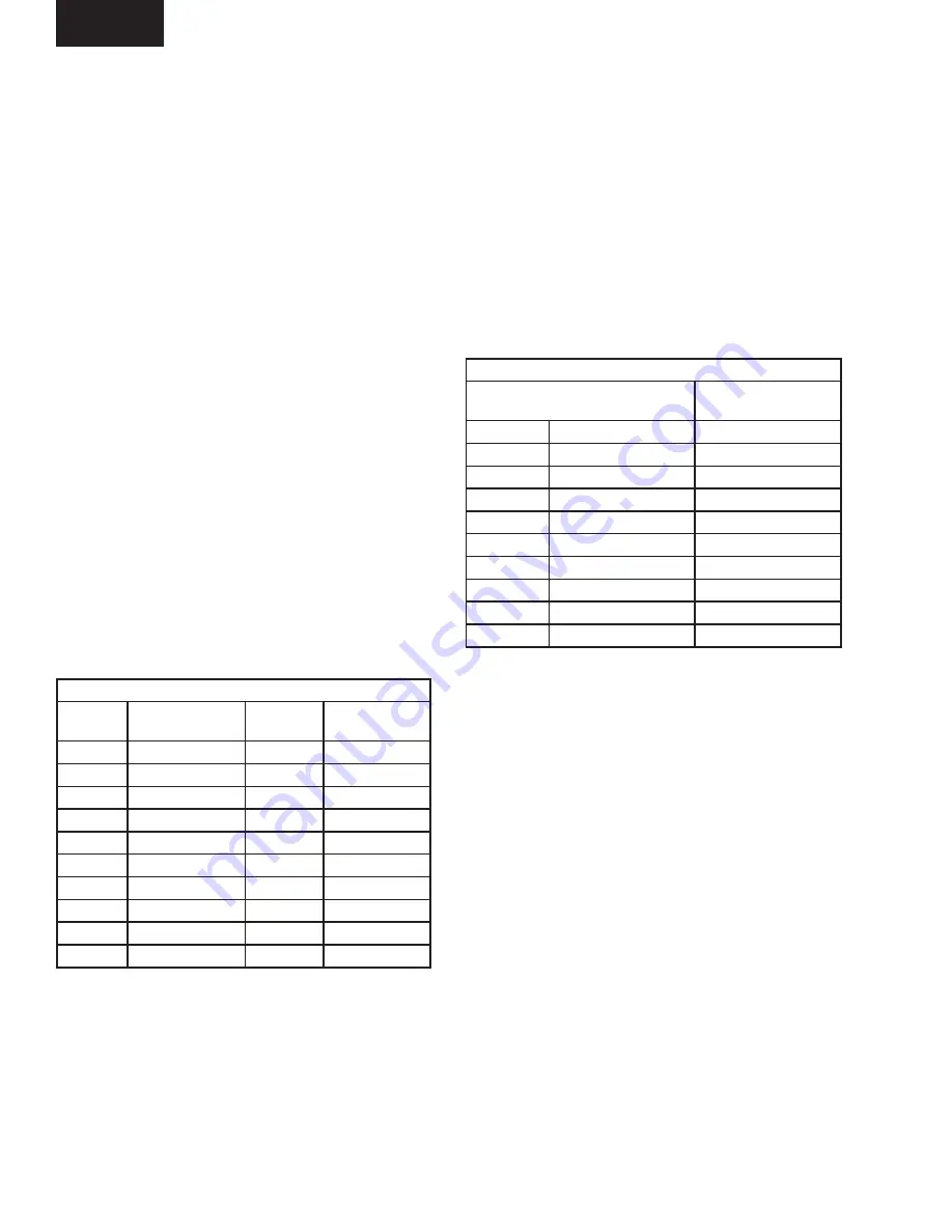
vs. output volts DC from the transducer. Table 23 shows
the relationship between the pressure applied to the duct
pressure trans duc er and the output voltage.
Building Pressure Transducer
The building pressure transducer is located in the re turn
air section of the unit. The purpose of this trans duc er is
to sense and convert the static pressure in the building
to a DC voltage. The DC voltage is then sent to the unit
controller and compare against the
Building
Pressure
setpoint
. The control wiring from the trans duc er is fac-
tory wired, but pneumatic tubing must be
Þ
eld supplied
and installed (refer to Installation section in manual).
The building pressure transducer measures differential
pressure between the pressure in the build ing and at-
mospheric pressure. When verifying trans duc er opera-
tion, the technician can insert a tee into the pneumatic
tubing to connect a manometer and verify the pressure
being applied to the transducer. Once this pressure is
known, a comparison can be made of the duct pressure
vs. output volts DC from the transducer. A practical and
quick check of this transducer can also be accomplished
by removing the pneumatic tubing lines from both high
and low side connections on the trans duc er. Since both
of the inputs will now be exposed to the same pressure,
the differential pressure will be zero, and output 2.5
VDC according to the Table 24.
ANALOG INPUT OPERATION
This section describes the control operation of the (13)
thirteen analog inputs. These inputs will be used by the
control to monitor and respond to unit temperatures,
pressures, enthalpy, etc. The connection “layout” for
the IO (inputs/outputs) is shown in the Primary Unit
Controller connection map in Figure 21. Notice that the
Þ
gure shows the Jack connection designated by “J”, and
the pin num ber located on the inside of the board dia-
gram. The input or output designations are shown on the
out side of the
Þ
gure. For example, J11 – 8 is jack eleven
- pin 8 and is AI5 (analog input 5). J13 – 6 is jack 13
- pin 6 and is AI14 (analog input 14). For example, AI5
(J11 – 8) is the input for Outside Air Relative Humidity,
and is used as part of the economizer control scheme.
AI13 (J13 – 8) is the input for Supply Air Temperature,
and is used for control in both the CV and VAV control
schemes. The analog inputs are also in the I/O tables in
Table 33 with descriptions for each input.
Return, Outside, Supply Air and Slab
Temperature
The temperature sensors are RTD sensors that can be
checked with an ohmmeter. Table 22 provides the re sis -
tance values for a given temperature in °F.
Duct Pressure Transducer
The duct pressure transducer is mounted in the return
air section of the unit on the panel wall. The purpose of
this transducer is to sense and convert the static pres sure
in the supply-side of the duct to a DC voltage. The DC
volt age is then sent to the unit controller and com pare
against the
Duct Static Pressure setpoint
. The control
wiring is factory wired, but pneumatic tubing must be
Þ
eld sup plied and installed (refer to Installation section
* 2.5 IWC Duct Transducer Available for FlexSys Option
TABLE 23 – *DUCT PRESSURE TRANSDUCER
OUTPUT TABLE
TEMPERATURE SENSOR OUTPUT TABLE
TEMP.
°F
OHMS
RESISTANCE
TEMP.
°F
OHMS
RESISTANCE
-20
751
80
1030
-10
777
90
1060
0
803
100
1090
10
830
110
1121
20
858
120
1152
30
885
130
1184
40
914
140
1216
50
942
150
1248
60
971
160
1281
70
1000
170
1314
TABLE 22 – TEMPERATURE SENSOR
RESISTANCE TABLE
DUCT PRESSURE TRANSDUCER OUTPUT TABLE
DIFFERENTIAL INPUT
PRESSURE - IWG
OUTPUT VOLTAGE
- VDC
0.5
0.25
0.5
1.0
0.50
1.0
1.5
0.75
1.5
2.0
1.00
2.0
2.5
1.25
2.5
3.0
1.50
3.0
3.5
1.75
3.5
4.0
2.00
4.0
4.5
2.25
4.5
5.0
2.50
5.0