661693-UIM-E-1212
Johnson Controls Unitary Products
7
SECTION IV: ELECTRIC HEATER
INSTALLATION
If the air handler requires electric heat, install the electric heat kit
according to the installation instructions included with the kit. After
installing the kit, mark the air handler nameplate to designate the heater
kit that was installed. If no heater is installed, mark the name plate
appropriately to indicate that no heat kit is installed.
Use only 6HK heater kits, as listed on Air Handler name plate and in
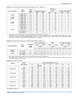
these instructions. Use data from Tables 4 through 9 for information on
required minimum motor speed tap to be used for heating operation,
maximum over-current protection device required and minimum electri-
cal supply wiring size required – for listed combination of Air Handler
and Heater Kit.
SECTION V: LINE POWER CONNECTIONS
Power may be brought into the unit through the supply air end of the
unit (top when unit is vertical) or the left side panel. Use the hole appro-
priate to the unit’s orientation in each installation to bring conduit from
the disconnect. The power lead conduit should be terminated at the
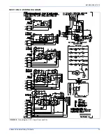
electrical control box. Refer to Tables 6 throught 9 to determine proper
wire sizing. Also see Figure 2. To minimize air leakage, seal the wiring
entry point at the outside of the unit.
All electrical connections to air handlers must be made with copper con-
ductors.
Direct connection of aluminum wiring to air handlers is
not approved.
If aluminum conductors are present, all applicable local and national
codes must be followed when converting from aluminum to copper con-
ductors prior to connection to the air handler.
If wire other than uncoated (non-plated), 75° C ambient, copper wire is
used, consult applicable tables of the National Electric Code (ANSI/
NFPA 70). The chosen conductor and connections all must meet or
exceed the amperage rating of the overcurrent protector (circuit breaker
or fuse) in the circuit.
Additionally, existing aluminum wire within the structure must be sized
correctly for the application according to National Electric Code and
local codes. Caution must be used when sizing aluminum rather than
copper conductors, as aluminum conductors are rated for less current
than copper conductors of the same size.
FIGURE 12:
Blower Delay Control Board
AHR/PSC CONTROL BOARD
FIGURE 13:
Line Power Connections
*1'
*1'
/8*
FIELD POWER WIRING
(208/230-1-60)
-803(5%$5
NO ELECTRIC HEAT
COMPONENT CODES
GND
–
GROUND LUG
CB
–
CIRCUIT BREAKER
CKT - CIRCUIT
CN
–
WIRE CONNECTOR/NUT
32:(5
6833/<
CKT 1
1 PHASE ELECTRIC HEAT OPTIONS:
SINGLE SOURCE POWER
MULTI-SOURCE POWER
MULTI-SOURCE POWER
WITH JUMPER BAR
TERMINAL BLOCK OR
CIRCUIT BREAKER
POWER
SUPPLY
POWER
SUPPLY
3 PHASE ELECTRIC HEAT POWER OPTIONS:
SINGLE SOURCE POWER
MULTI-SOURCE POWER
2 CIRCUITS ON13KW-20KW
3 CIRCUITS ON 25KW
TERMINAL BLOCK OR
CIRCUIT BREAKER
CKT 2
CKT 1
POWER
SUPPLY
CB
CB
CB
CB
CB
2 CIRCUITS ON13KW-20KW
3 CIRCUITS ON 25KW
POWER
SUPPLY
*1'
*1'
*1'
*1'
POWER
SUPPLY
L1
L2
L1
L2
L1
L2
CKT 2
CKT 3
L1
L2
L1
L2
CN
CN
CB
CB
CB
L1
L2
L3
L1
L2
L3
L1
L2
L3
Содержание 41HP AHR 42C
Страница 1: ......


