background image

661693-UIM-E-1212

10

Johnson Controls Unitary Products

d

AHR30B
AHR42C

6HK(0,1)6500206

10.0

14.6

16.3

15

20

12

12

6HK(0,1)6500506

20.0

25.4

28.8

30

30

10

10

6HK(0,1)6500806

32.0

38.4

43.8

40

45

8

8

6HK(0,1)6501006

40.0

47.1

53.8

50

60

6

6

6HK(1,2)6501306

52.0

60.1

68.8

70

70

6

4

6HK(1,2)6501506

60.0

68.8

78.8

70

80

4

4

AHR36B
AHR48D

6HK(0,1)6500206

10.0

14.6

16.3

15

20

12

12

6HK(0,1)6500506

20.0

25.4

28.8

30

30

10

10

6HK(0,1)6500806

32.0

38.4

43.8

40

45

8

8

6HK(0,1)6501006

40.0

47.1

53.8

50

60

8

6

6HK(1,2)6501306

52.0

60.1

68.8

70

70

6

4

6HK(1,2)6501506

60.0

68.8

78.8

70

80

4

4

6HK(1,2)6501806

72.0

81.8

93.8

90

100

4

3

6HK(1,2)6502006

80.0

90.4

103.8

100

110

3

2

AHR60D

6HK(0,1)6500206

10.0

14.6

16.3

15

20

12

12

6HK(0,1)6500506

20.0

25.4

28.8

30

30

10

10

6HK(0,1)6500806

32.0

38.4

43.8

40

45

8

8

6HK(0,1)6501006

40.0

47.1

53.8

50

60

8

6

6HK(1,2)6501306

52.0

60.1

68.8

70

70

6

4

6HK(1,2)6501506

60.0

68.8

78.8

70

80

4

4

6HK(1,2)6501806

72.0

81.8

93.8

90

100

4

3

6HK(1,2)6502006

80.0

90.4

103.8

100

110

3

2

6HK(1,2)6502506

100.0

112.1

128.8

125

150

2

1

1. (0,1) - maybe 0 (no circuit breaker) or 1 (with circuit breaker).
2. (1,2) maybe 1 (with circuit breaker, no breaker jumper bar) or 2 (with circuit breaker & breaker jumper bar).

3. MOP = Maximum Overcurrent Protection device; must be HACR type circuit breaker or time delay fuse.
4. Stated sizes are for 75°C, copper wire only.  If wire other than non-plated, 75°

C

 ambient, copper wire is used, consult applicable tables of the 

NEC and local codes.

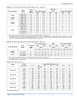
TABLE 6: 

ELECTRICAL DATA FOR SINGLE SOURCE POWER SUPPLY:  208/230-1-60 (Continued)

Air Handler Models

Heater 

Models

1,2

Heater

Amps 

@240V

Field Wiring

Min. Circuit Ampacity

MOP.

3

Min Wire Size (AWG)

4

208V

230V

208V

230V

208V

230V

TABLE 7: 

ELECTRICAL DATA FOR MULTI-SOURCE POWER SUPPLY: 208/230-1-60

Air 

Handlers 

Models

Heater

Models

Total 

Heater 

Amps 

@240V

Min. Circuit Ampacity

MOP

1

Min. Wire Size (AWG)

2

208V

230V

208V

230V

208V

230V

Circuit

Circuit

Circuit

1st

3

2nd

3rd

1st

3

2nd

3rd

1st

3

2nd

3rd

1st

3

2nd

3rd

1st

3

2nd

3rd

1st

3

2nd

3rd

AHR24B

6HK16501306

52.0

20.6 37.6

-

23.4 43.3

-

25

40

-

25

45

-

10

8

-

10

8

-

6HK16501506

60.0

23.5 43.3

-

26.8 50.0

-

25

45

-

30

50

-

10

8

-

10

8

-

AHR30B
AHR42C

6HK16501306

52.0

22.6 37.6

-

25.4 43.3

-

25

40

-

30

45

-

10

8

-

10

8

-

6HK16501506

60.0

25.5 43.3

-

28.8 50.0

-

30

45

-

30

50

-

10

8

-

10

8

-

AHR36B
AHR48D

6HK16501306

52.0

22.6 37.6

-

25.4 43.3

-

25

40

-

30

45

-

10

8

-

10

8

-

6HK16501506

60.0

25.5 43.3

-

28.8 50.0

-

30

45

-

30

50

-

10

8

-

10

8

-

6HK16501806

72.0

42.8 39.0

-

48.8 45.0

-

45

40

-

50

45

-

8

8

-

8

8

-

6HK16502006

80.0

47.1 43.3

-

53.8 50.0

-

50

45

-

60

50

-

8

8

-

6

8

-

AHR60D

6HK16501306

52.0

22.6 37.6

-

25.4 43.3

-

25

40

-

30

45

-

10

8

-

10

8

-

6HK16501506

60.0

25.5 43.3

-

28.8 50.0

-

30

45

-

30

50

-

10

8

-

10

8

-

6HK16501806

72.0

42.8 39.0

-

48.8 45.0

-

45

40

-

50

45

-

8

8

-

8

8

-

6HK16502006

80.0

47.1 43.3

-

53.8 50.0

-

50

45

-

60

50

-

8

8

-

6

8

-

6HK16502506

100

47.1 43.3 21.7 53.8 50.0 25.0

50

45

25

60

50

25

6

6

10

6

8

10

1. MOP = Maximum Overcurrent Protection device; must be HACR type circuit breaker or time delay fuse.
2. Stated sizes are for 75°C, copper wire only.  If wire other than non-plated, 75°C ambient, copper wire is used, consult applicable tables of the NEC and local codes.
3. 1st Circuit includes the blower motor amps.

Содержание 41HP AHR 42C

Страница 1: ......

Страница 2: ...ervice personnel can perform basic maintenance functions such as cleaning and replacing the air filters When work ing on heating cooling equipment observe precautions in the man uals and on the labels...

Страница 3: ...secondary drain It should be piped to a loca tion that will give the occupant a visual warning that the primary drain is clogged If the secondary drain is not used it must be capped 5 When an evaporat...

Страница 4: ...ort bracket See Figure 5 This positions the deflector below the feeder tubes to channel the condensate to the drain pan DUCT FLANGES Four flanges are provided to attach ductwork to the furnace These f...

Страница 5: ...is recommended a block off plate approximately 8 in height and running the full width of the ple num be attached to the supply opening Please refer to Figure 8 as a visual aid The use of this block o...

Страница 6: ...ed and piped to a location that will give the occupant a visual warning that the primary drain is clogged If the secondary drain is not used it must be capped The drain pan connections are designed to...

Страница 7: ...um wiring to air handlers is not approved If aluminum conductors are present all applicable local and national codes must be followed when converting from aluminum to copper con ductors prior to conne...

Страница 8: ...require ments Read and heed all unit caution labels It is possible to vary the amount of electric heat turned on during the defrost cycle of a heat pump Standard wiring will only bring on the first s...

Страница 9: ...4 11 5 32 0 39 2 3 1 3 8 9 4 11 5 6HK 1 2 6501506 14 4 10 8 13 2 36 9 45 1 3 6 4 4 10 8 13 2 6HK 1 2 6501806 17 3 13 0 15 9 44 3 54 2 6 5 7 9 13 0 15 9 6HK 1 2 6502006 19 2 14 4 17 6 49 2 60 2 7 2 8...

Страница 10: ...and local codes TABLE 6 ELECTRICAL DATA FOR SINGLE SOURCE POWER SUPPLY 208 230 1 60 Continued Air Handler Models Heater Models1 2 Heater Amps 240V Field Wiring Min Circuit Ampacity MOP 3 Min Wire Siz...

Страница 11: ...L DATA FOR MULTI SOURCE POWER SUPPLY 208 230 3 60 Air Handler Models Heater Models Total Heater Amps 240V Min Circuit Ampacity MOP1 Min Wire Size AWG 2 208V 230V 208V 230V 208V 230V Circuit Circuit Ci...

Страница 12: ...t AHR18B3XH21 High 1145 1100 1055 1005 930 845 725 Medium 755 750 725 665 605 485 435 Low 680 655 625 585 540 395 300 AHR24B3XH21 High 1305 1285 1225 1175 920 915 835 Medium 930 920 890 845 705 760 50...

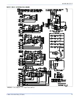
Страница 13: ...661693 UIM E 1212 Johnson Controls Unitary Products 13 SECTION X WIRING DIAGRAM FIGURE 15 Wiring Diagram PSC Single Phase Heat Kits...

Страница 14: ...NT CODES GND EQUIPMENT GROUND FL FUSIBLE LINK HE HEATING ELEMENT LS LIMIT SWITCH REL RELAY FIELD POWER WIRING 208 230V FACTORY WIRING 208 230V FACTORY WIRING LOW VOLTAGE L1 L2 L3 L1 L2 L3 GND GND GND...

Страница 15: ...661693 UIM E 1212 Johnson Controls Unitary Products 15 SECTION XI TYPICAL THERMOSTAT CONNECTIONS FIGURE 17 Typical Wiring Diagram PSC...

Страница 16: ...dry bulb temperature Return air dry bulb temperature Temperature drop 1 2 3 4 5 Low Medium Low Medium Medium High High A B C D Outside air dry bulb temperature Return air wet bulb temperature Supply a...

Страница 17: ...he thermostat noting and correcting any problems Operate the unit through mechanical heating cycles from the thermostat noting and correcting any problems Operate the unit through emergency heating cy...

Страница 18: ...o change without notice Published in U S A 661693 UIM E 1212 Copyright 2012 by Johnson Controls Inc All rights reserved Supersedes 661693 UIM D 1012 York International Corp 5005 York Drive Norman OK 7...

Отзывы: