

©York Survey Supply Centre 2018
Ref:.. \operat98\instructions 18\343660.qxp 05-01-18
Datalogging Light Meter
Introduction
This digital datalogging light meter is a precision instrument used to
measure luminance by Lux or Footcandles (FC). It meets the CIE
photopic spectral response standard. When not in use, the instrument
should be kept in the carry case and lens cap put onto the lens to
protect it from damage.
Features
> 4 Measuring Ranges Lux
> 4 Measuring Ranges Footcandles
> Silicon Photo Diode Sensor with a Spectral Response Filter Fully
Cosine Corrected
> High accuracy and rapid response
> Data Hold, Peak Hold, Min/Max Memory, Relative Function
> 56mm Hight Contrast LCD with 41 Segment Bargraph, Function
Indicators and Backlight
> Auto-Power Off after 15 minutes with User Disable
> USB output
> 99 Individual Record Memory independent of the Datalogger
> Datalogger Capacity of 16,000 Readings
> Accessories Included: Carry Case, Software and USB Connection
Cable
Specifications
> 4 Measuring Ranges for Lux: 0Lux to 400Lux, 4KLux, 40KLux,
400KLux
> 4 Measuring Ranges for Footcandles: 0FC to 40FC, 400FC, 4KFC,
40KFC
> Accuracy: ±3% rdg ±0.5% f.s. (<10,000Lux). ±4% rdg ±10d.
(>10,000Lux)
> Sampling rate of 1.5 times per second (selectable rate for data
logging)
> Operating temperature and humidity: 0°C ~ 40°C and
0%RH ~ 80%RH
> Storage conditions: -10°C ~ 50°C and 0%RH ~ 70%RH
> Power source: 1x 9V battery
> Length of Connection Lead for Light Sensor: 1m
> Light Sensor Dimensions: 115L x 80W x 20H (mm)
> Meter Dimensions: 230L x 80W x 50H (mm)
> Weight of Unit: 390g
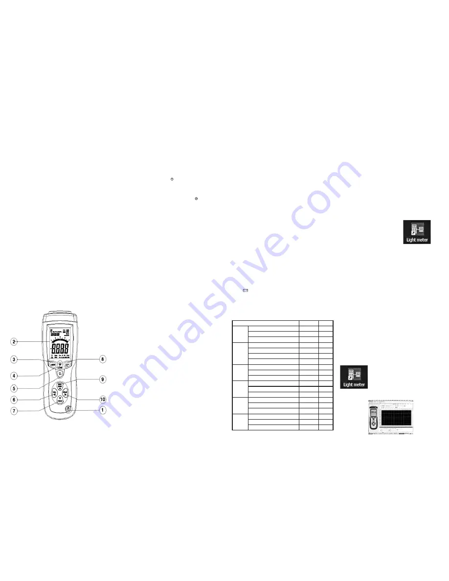
Function Buttons
1. Power On/Off Button
3. UNITS Button
4. Backlight and LOAD Button
5. REC/SETUP Button
6. PEAK Button
7. HOLD Button
8. RANGE/APO Button
9. MIN/MAX Button
10. REL Button
Operating Instructions
Power On/Off, Auto Power Off and Display Backlight
To turn the meter on, press the
yellow power button
(No 1) on the
bottom of the unit. If auto power off is disabled, press the button again
to turn the meter off.
At first power on the instrument defaults to a 15 min “Auto Power OFF”.
To disable auto power off, press and hold
REC/Setup
button (No 5)
then press
RANGE/APO
button (No 8) until this symbol disappears
from the bottom left of the display. Repeat to re-enable the auto power
off.
To illuminate the backlight, press the
LOAD
button (No 4). Repeat to
turn off the backlight.
Selection of Measurements and Ranges in Lux or Footcandles
To change measurement units, press the
UNITS
button (No 2). This
changes the displayed values from Lux to Footcandles or vice versa.
1FC = 10.76Lux.
There are 4 measuring ranges for Lux and Footcandles. Press
RANGE/APO
button (No 8) to scroll through the measuring ranges.
Should the display show “
OL
” then the range selected is too low for the
measured value. Select the next range up. Repeat until the instrument
displays a value. The selected range is displayed below the main
reading.
Connect the sensor to the instrument. Remove the black plastic cover
protecting the sensor and the instrument will display the measured
value.
To Set Time, Date and Datalogging Sampling Time
The time, date and sampling rate has to be set for recording and
storing measurements.
To enter this setup mode, press and hold down for 5 seconds the
REC/Setup
button (No 5) and the
UNITS
button (No 3) simultaneously.
The word
‘Time’ and the hour digits
should be flashing. You are now
in the setup mode.
The 4 keys (No’s 6, 7, 10 and 9) with arrows are used to change the
data and scroll through the setup menu. The Hour is the first part of the
program and is flashing. Use the up/down arrow buttons (No’s 7 and 9)
to increase or decrease the displayed hour. When the hour is correct,
press the right arrow button (No 10) which then moves the setup to
Minutes. Again using up/down arrow buttons (No’s 7 and 9) change the
displayed digits to the correct value. Repeat this process to set
Seconds, Sampling Time, Month, Date and Year. Note: The sampling
time is for the datalogger recording only. The true sampling rate of the
instrument is 1.5 times per second. To exit the setup program, press
and hold down for 5 seconds the
REC/Setup
button (No 5) and the
UNITS
button (No 3) simultaneously.
Data Hold
This function allows the current reading to be frozen on the display.
Press
HOLD
button (No 7) to activate. An indicator in the bottom of the
display will show
Manu Hold
. Press
HOLD
again to cancel data hold
and the instrument will display current measured values.
Minimum/Maximum Values
This function is activated by pressing
MIN/MAX
button (No 9) and will
display the minimum and maximum values since the instrument was
switched on. The first value is the maximum measured value with a
Manu Max
indicator shown in the bottom of the display. Press the
MIN/MAX
button again. The displayed value with
Manu Min
indicator
shown in the bottom of the display. Press
MIN/MAX
again to cancel
data hold and the instrument will display current measured values.
Peak Hold
This function’s purpose is to display only the highest or lowest
measured value and is activated by pressing the
PEAK
button (No 6).
The first value is the highest measured value with a
Manu Pmax
indicator shown in the bottom of the display. Press the
PEAK
button
again. The displayed value is the lowest measured value with
Manu
Pmin
indicator shown in the bottom of the display. Press
PEAK
again
to cancel peak measuring and the instrument will display current
measured values.
Relative Readings
This function is used to read measured values compared to a
memorised value. When a value is established, press the
REL
button
(No 10). The displayed values will then be deviations to the relative
stored value and shown as plus or negative value with a
Manu
indicator shown in the bottom of the display. Press the
REL
button
again to exit this function and the instrument will display current
measured values.
Recall 99 Memory Function
The instrument has an independent memory separate to the
datalogger. It is used to memorise individual measured values for recall
without using a computer connection. To memorise a reading, press
REC/Setup
button (No 5). In the top right hand corner of the display an
indicator will appear “
MEM 01
”. This confirms the measured value has
been memorised as record number 1. Press
REC/Setup
again and the
indicator will display as “
MEM 02
”. This confirms the measured value
has been memorised as record number 2. This can be repeated for up
to 99 readings.
To recall the readings from the memory, press and hold for 5 seconds
the
LOAD
button (No 4). Using the up and down buttons (No’s 7 and 9)
will allow you to scroll through each memorised value.
To clear the memory, press and hold for 5 seconds the
LOAD
and
REC/Setup
buttons at the same time.
MEM CL
will appear in the top
right hand corner of the display whilst the memory is cleared. When the
memory is clear, the instrument will revert back to normal measuring
mode.
To read the “Recall 99 Memory” via the software. On the top menu line
click on
Mem(M)
. The software will now download the memorised
values and, when complete, auto open a new window listing the
reading Number, Measured Value with the Date and Time the
measurement was memorised. This data can be saved or printed.
Low Battery Indication
When the battery power falls below the required voltage, a battery
symbol
will appear on the display. To change the battery, slide the
back cover off, disconnect the expired battery and replace.
EPROM Memory Backup
The EPROM has a 2nd battery backup so no data is lost due to main
battery changes.
Recommended Illumination Values
Maintenance and Calibration
In order to ensure accurate readings, the lens should be cleaned using
a damp cloth to remove any dust or dirt. Do not store the instrument
where the temperatures are excessively low or high or the humidity is
excessively high. This should be considered especially when leaving
instruments in vehicles.
Re-calibration of this instrument will vary due to operating conditions
and regulations. It is recommended that the meter is re-calibrated at
least once every 12 months. York Survey Supply Centre offers a fully
traceable calibration service to national standards. Please call our
technical helpline for current prices: 01904 692723.
Installing the Software
Start Windows and insert the CD into the CD drive. Install Wizard
should detect and install the software.
If install wizard does not appear automatically, go to
START
at the
bottom of the desktop, then
Run...
Browse for
Light Meter (D:)
which
is the name of the software.
Click on
Light Meter (D:)
. This will open up the files stored within the
CD. Open the
SETUP
file and follow the instructions to install the
software.
Once this is complete you will see this icon,
appear on your desktop. The installation
was successful, but before you can use the
software you need to install the hardware
drivers.
Do not remove the CD.
Installing the Hardware Drivers
You do not need to install the hardware drivers if you already have
installed it - the following Datalogging instruments all use the
same program:
SL-8851 USB Logging Sound Level Meter
SL-8852 Datalogging Sound Level Meter
LX-1309 USB Logging Lux Meter
With the CD for the software still in the CD drive, turn the instrument
on, then connect the meter to the computer using the USB cable
supplied.
A message will appear to show the computer has detected new
hardware in the USB port. Double click on this message. A new window
will appear asking you to install the hardware. On this window click ‘
No,
not this time
’, as you do not need to connect to the windows update.
Follow the instructions to install the hardware, but
before
you press
FINISH check that it reads ‘
CP2101 USB Composite Device
’ in the
window (this is the first hardware driver). Click
FINISH
.
The window will now ask to install the hardware; this is to install the
second driver. Install in the same way as you did for the previous driver.
In the last window it should show ‘
CP2101 USB to UART Bridge
Controller
’. Click FINISH and both hardware drivers should now be
installed.
To un-install the drivers (in the “add or remove programs”) you will not
find two separate drivers. You will find one driver called ‘
CP210x USB
to UART Bridge Controller
’ . This is because both drivers are saved
together, so by un-installing this you are, in fact, un-installing both the
drivers.
Using the Software
Connect the instrument to the computer with the USB cable. Open the
software by clicking on the icon.
If there is no connection the software will display
OFFLINE
in the
instrument image. Check the connections are correct and plugged in.
LOCATIONS
Lux
FC
OFFICE
Conference, Reception room
200 ~ 750
18 ~ 70
Clerical work
700 ~ 1,500
65 ~ 140
Typing drafting
1,000 ~ 2,000 93 ~ 186
FACTORY
Visual work at production line
300 ~ 750
28 ~ 70
Inspection work
750 ~ 1,500
70 ~ 140
Electronic parts assembly line
1,500 ~ 3,000 140 ~ 279
Packing work, Entrance passage
150 ~ 300
14 ~ 28
HOTEL
Public room, Cloakroom
100 ~ 200
9 ~ 18
Reception
200 ~ 500
18 ~ 47
Cashier
750 ~ 1,000
70 ~ 93
STORE
Indoors Stairs Corridor
150 ~ 200
14 ~ 18
Show window, Packing table
750 ~ 1,500
70 ~ 140
Forefront of show window
1,500 ~ 3,000 140 ~ 279
HOSPITAL
Sickroom, Warehouse
100 ~ 200
9 ~ 18
Medical Examination Room
300 ~ 750
28 ~ 70
Operating room, Emergency treatment
750 ~ 1,500
70 ~ 140
SCHOOL
Auditorium, Indoor Gymnasium
100 ~ 300
9 ~ 28
Classroom
200 ~ 750
18 ~ 70
Laboratory, Library, Drafting room
500 ~ 1,500
47 ~ 140


