background image

Triggering

3

2

1

4

5

6

7

8

9

10

11

12

13

14

15

16

17

18

19

App

Index

6-73

IM 701310-01E

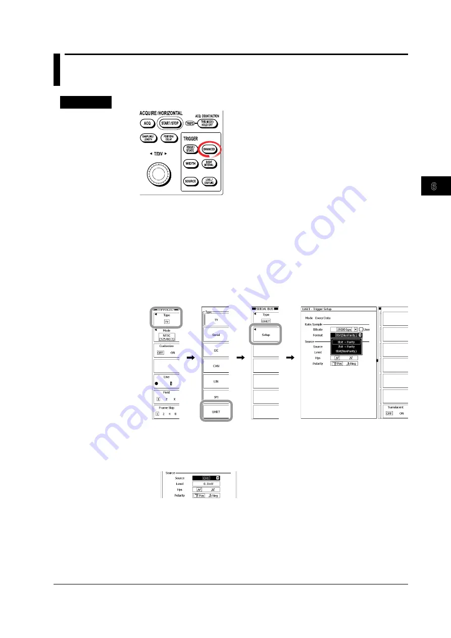
6.19  Triggering on a UART Signal

Procedure


1.

  Press 

ENHANCED

.

2.

  Press these soft keys: 

Type

 > 

UART

 > 

Setup

.

The Setup dialog box appears.

Setting the Bit Rate and Format

3.

  Use the 

rotary knob

 and 

SET

 to select the bit rate from 115200bps to 1200bps.

If you select the 

User

 check box, you will be able to set the bit rate from 1000bps to 

200000bps using the 

rotary knob

 and 

SET

.

4.

  Use the 

rotary knob

 and 

SET

 to select the format from 8bit + Parity to 

8bit(NonParity).

Setting the Trigger Level, Hysteresis, and Polarity

5.

  Use the 

rotary knob

 and 

SET

 to select the source from CH1 to CH4.

6.

  Use the 

rotary knob

 and 

SET

 to set the level, hysteresis, and polarity.


Содержание DL9000 Series

Страница 1: ...IM 701310 01E 8th Edition Digital Oscilloscope DL9040 DL9140 DL9240 Series...

Страница 2: ...sing YOKOGAWA products YOKOGAWA provides registered users with a variety of information and services Please allow us to serve you best by completing the product registration form accessible from our h...

Страница 3: ...701310 01E 8th Edition applies to DL9000 digital oscilloscope with firmware version 4 40 or later If the most recent firmware version is not running on your DL9000 not all of the features described i...

Страница 4: ...1E Revisions 1st Edition June 2005 2nd Editon August 2005 3rd Editon January 2006 4th Editon June 2006 5th Editon Decenber 2006 6th Editon August 2007 7th Edition June 2008 Edition June 2008 8th Editi...

Страница 5: ...W channel 701312 DL9240 Digital Oscilloscope 4 channels 10 GS s 1 5 GHz max 2 5 MW channel 701313 DL9240L Digital Oscilloscope 4 channels 10 GS s 1 5 GHz max 6 25 MW channel Power cord D UL CSA Standa...

Страница 6: ...cover B8080EM 500 MHz Passive Probe PB500 701943 4 probes UL CSA Standard A1006WD VDE Standard A1009WD BS Standard A1054WD AS Standard A1024WD D F Q R Power Cord one of the following power cords is s...

Страница 7: ...igh voltage high voltage 100 1 probe 701944 DC to 400 MHz bandwidth 1000 V 400 MHz bandwidth 1000 V bandwidth 1000 V 1000 Vrms 1 2 m in length 701945 DC to 250 MHz bandwidth 1000 V 250 MHz bandwidth 1...

Страница 8: ...failure to comply with these requirements The Following Symbols Are Used on This Instrument Warning handle with care Refer to the user s manual or service manual This symbol appears on dangerous loca...

Страница 9: ...ng so poses a potential shock hazard Do Not Operate with Defective Protective Grounding or Fuse Do not operate the instrument if the protective earth or fuse might be defective Make sure to check them...

Страница 10: ...EC marking requirement This marking indicates that you must not discard this electrical electronic product in domestic household waste Product Category With reference to the equipment types in the WEE...

Страница 11: ...at is important for proper operation of the instrument Subheadings On pages that describe the operating procedures in chapters 3 through 18 the following symbols are used to distinguish the procedures...

Страница 12: ...Connect probes Initialization Auto setup Vertical axis Horizontal time axis Triggering Acquire waveforms including GO NO GO Display waveforms and information Waveform Computation Analysis and Search...

Страница 13: ...2 Installing the Instrument 3 3 3 3 Connecting the Power 3 5 3 4 Connecting the Probe 3 8 3 5 Compensating the Probe Phase Correction 3 11 3 6 Setting the Date and Time 3 13 Chapter 4 Basic Operations...

Страница 14: ...Triggering on a CAN Bus Signal 6 56 6 17 Triggering on a LIN Bus Signal 6 67 6 18 Triggering on a SPI Bus Signal 6 69 6 19 Triggering on a UART Signal 6 73 6 20 Activating a Trigger on an Event Cycle...

Страница 15: ...eforms on the XY Display 10 36 10 7 Performing FFT Analysis 10 39 10 8 Displaying a Histogram Trend or List of the Automatically Measured Waveform Parameters 10 45 10 9 Displaying the Frequency Distri...

Страница 16: ...Waveforms Automatically 14 7 14 7 Displaying the Acquisition Time of a Loaded Waveform 14 8 Chapter 15 Ethernet Communications Optional 15 1 Connecting the DL9000 to the Network 15 1 15 2 Setting the...

Страница 17: ...19 Specifications 19 1 Models 19 1 19 2 Input Section 19 1 19 3 Trigger Section 19 2 19 4 Time Axis 19 4 19 5 Display Section 19 4 19 6 Functions 19 4 19 7 Built in Printer B5 option 19 7 19 8 Auxili...

Страница 18: ...H CH 1 POWER COMP CH 2 CH 3 CH 4 LCD display ESC key Soft keys For a description of the display contents see chapter 8 Used to select items on the soft key menu that appears on the screen during setup...

Страница 19: ...he GO NO GO determination output signal See section 16 4 GO NO GO output connector Used to supply power to an FET probe or a current probe made by YOKOGAWA See section 3 4 Probe power terminal option...

Страница 20: ...s effect when signal acquisition is restarted This knob includes a push switch and can be pressed to change the resolution of the setting When the knob is pressed lighting the Fine indicator the resol...

Страница 21: ...ed by the PARAM key displays a menu for the telecom test WINDOW 1 key WINDOW 2 key Sections 10 5 to 10 9 Display a menu for serial bus signals analysis XY display FPT analysis waveform parameter histo...

Страница 22: ...relating to calibration network computer interface settings date and time message language click sound self test and storage media formatting Displays system information which options are installed a...

Страница 23: ...Input channel status Coupling Scale Probe attenuation rate Trigger position Computing Reference waveform status Signal acquisition count Trigger position mark Ground level mark Vertical position mark...

Страница 24: ...Normal waveform area Zoom waveform area Z1 waveform area Z2 waveform area V div of Z1 V div of Z2 Displayed only if the waveform is zoomed vertically Displayed record length of the Normal waveform Zo...

Страница 25: ...TT Pre AMP Cross Point SW A D Acquisition Memory Data Processing Memory CPU Color LCD Trigger Circuit Time Base Trigger Output Trigger Comparator Output GO NO GO Output optional CH2 CH3 CH4 Primary Me...

Страница 26: ...eforms computed from input waveforms or reference waveforms In the calculation equation that can be set in the menu for channels 1 to 4 is fixed being the input waveform of the input channel being set...

Страница 27: ...nput signal is measured with as large an amplitude as possible The DL9000 uses 8 bit A D converters to sample the input signal at a resolution of 250 levels LSB The waveforms are displayed using 25 le...

Страница 28: ...or of the vertical control circuit You can use this setting to check the ground level on the screen Vertical control circuit Input terminal 1 M Vertical control circuit Input terminal DC1 M Vertical c...

Страница 29: ...Offset Cancel is OFF When Offset Cancel is ON Vertical position mark GND level mark Inverted Waveform Display This inverts the waveform display about the Position value as center The inversion applie...

Страница 30: ...ayed waveform being updated by a trigger update mode the waveform is displayed in roll mode In roll mode as new data is captured the oldest values are deleted from the screen as the waveform scrolls f...

Страница 31: ...eresis amount Trigger level Trigger level refers to the level at which a trigger is activated when the trigger source passes the certain level With simple triggers such as the edge trigger described l...

Страница 32: ...ivated when the normalized condition changes L H H CH1 CH2 State CH1 H CH2 L CH3 CH4 X AND Clock None Polarity Enter L low level H high level Trigger CH1 CH2 H H L L L State condition false State cond...

Страница 33: ...ter than specified time T1 or longer than specified time T2 Out of range A trigger when the pulse width exceeds the specified time Time out Trigger source More than Trigger t T1 t T1 Trigger source Le...

Страница 34: ...CH2 H H L L L L H H CH1 CH2 CH1 CH2 H H L L L H H CH1 CH2 State CH1 H CH2 L CH3 CH4 X AND Clock None Polarity False More than L low level H high level Trigger CH1 CH2 L H L State CH1 H CH2 L CH4 X AND...

Страница 35: ...or F8 option is required to analyze I2C bus signals CAN A trigger function for capturing CAN bus signals Controller Area Network CAN is a serial communication protocol that has been standardized inter...

Страница 36: ...1 Trigger Determination time T1 Trigger Event t1 t2 t3 T1 t1 T2 T2 t2 t3 T1 Trigger Determination time T1 T2 Event t1 t2 t3 T1 t1 T2 T2 t2 t3 T1 Trigger Determination time T1 T2 Trigger Event t1 t2 t3...

Страница 37: ...o as the timeout time the displayed waveforms are automatically updated Auto Level Mode The displayed waveforms are updated in the same way as in auto mode In the case of an Edge trigger if the trigge...

Страница 38: ...he specified edge is detected The set time is from 0 to 10 s Edge Count After the trigger occurs delay until the specified edge has been detected a certain number of times Trigger Hold off For the pro...

Страница 39: ...oise can be reduced giving a more stable waveform display However this setting can make the trigger point less precise reducing the trigger sensitivity so that a trigger source of low amplitude may fa...

Страница 40: ...e sample rate remains high irrespective of the time axis setting It is also useful when you want to detect glitches narrow pulse signals or display an envelope of a modulating signal Envelope curve Av...

Страница 41: ...cases the record length is changed as a result for example of a changed time axis setting see Appendix 1 Sampling Mode For the procedure see sections 7 4 to 7 6 Depending on the time axis setting you...

Страница 42: ...ampling which enables the signal before the trigger point trigger position see section 2 4 to be observed Interleave Mode The sample rate in realtime sampling mode can be increased to 5 GS s by sampli...

Страница 43: ...ivated and signals are acquired it is impossible to stop the measurement in time when an abnormal waveform appears newer waveforms appear on the screen Normally abnormal waveforms in the past cannot b...

Страница 44: ...oad a polygonal zone created on a computer Waveform Parameter Search For the procedure see sections 11 5 to 11 7 From the history waveforms you can search for waveform meeting or not meeting specified...

Страница 45: ...d A2 Main Main Z2 Z1 Z1 Z2 Main Z1 or Z2 Z1 or Z2 Main Z1 or Z2 or Z1 or Z2 Z1 Z2 or Main or Z1 or Z2 Main or Main or Z1 Z2 Z1 or Z2 Main Main Z1 Z2 Z1 Z2 A1 or A2 When the Main normal waveform and Zo...

Страница 46: ...ne wave Sine interpolation is suitable for observing sine waves or similar waves Linear Interpolation Linearly interpolates between two points Pulse Interpolation Interpolates between two points in a...

Страница 47: ...te allowing for easy comparison against the updated waveform The snapshot waveform can be printed as screen image data but cannot be used for cursor measurement automated measurement of waveform param...

Страница 48: ...tting a voltage signal and current signal Integration For the procedure see section 9 4 This integrates the selected waveform Taking the specified integration start point as 0 the entire region is cal...

Страница 49: ...carried out but manual scaling can also be selected Auto scaling automatically determines from the computed waveform the center line level1 Center in the vertical axis direction of the screen area and...

Страница 50: ...ference between the vertical cursors and the reciprocal of the time difference can be measured A computation formula using the cursor measurement values can also be set and the result displayed H V cu...

Страница 51: ...ent values subjected to statistics processing Cnt The following three statistical processing methods are available Normal Statistical Processing Statistical processing is carried out while acquiring w...

Страница 52: ...eviation Tcrossing1 First crossing point average time value Tcrossing2 Second crossing point average time value Vcrossing Voltage at the point of intersection of the rising edge and falling edge Cross...

Страница 53: ...relationship between the two input signals can be observed Simultaneous observation of X Y waveforms and normal T Y waveforms waveform display using time axis and level is possible It is also possible...

Страница 54: ...gher spectral level accuracy When the waveform being analyzed is a continuous signal select the whichever of the Hanning window and flattop window is more suitable for the application The number of po...

Страница 55: ...isplayed in a list Accumulated Histogram Display For the procedure see section 10 9 For a repeatedly captured signal a frequency distribution histogram Vertical Horizontal is shown for the specified r...

Страница 56: ...Communication interface PC DL9000 Saving and Recalling Data on a Network Drive For the procedure see section 15 3 In the same way as on the internal storage media measurement and setting data can be s...

Страница 57: ...some of the settings are not initialized see section 4 4 To initialize all settings excluding the date time setting display ON OFF is initialized to their factory defaults turn ON the power while hold...

Страница 58: ...sections 13 4 to 13 6 Setup data measurement data and snapshot accumulated waveforms can be saved to or loaded from a selected storage medium Saving Screen Image Data For the procedure see section 13...

Страница 59: ...ed on the power cord The cord should be kept away from any heat sources When unplugging the power cord from the outlet never pull by the cord itself Always hold and pull by the plug If the power cord...

Страница 60: ...d at locations 1 and 2 in the figure below When changing the position of the handle press the left and right attachment the blue cover and release the lock as in the figure below before moving the han...

Страница 61: ...LIN G LENG TH POSI TION DELA Y T D IV TRIGGER EDG E STA TE ENH ANC ED WID TH EVEN T INTE RVAL SOU RCE INT ENS ITY ACC UM FOR M ACC UM ANALY SIS XY WIN DOW 1 WIN DOW 2 CUR SOR TEL ECO M TES T PAR AM VE...

Страница 62: ...irect sunlight or near heat sources Where an excessive amount of soot steam dust or corrosive gas is present Near strong magnetic field sources Near high voltage equipment or power lines Where the lev...

Страница 63: ...be compromised If an AC outlet that conforms to the accessory power cord is unavailable and protective grounding cannot be furnished do not use the instrument Connecting the Power Cord 1 Check that b...

Страница 64: ...el OFF ON Powering off CAUTION Abruptly turning the main power switch off or unplugging the power cord while saving data or printing with the built in printer may damage the built in printer or corrup...

Страница 65: ...strument to warm up for at least 30 minutes after turning ON the power switch After warm up is complete perform calibration see section 4 8 If Auto Calibration is on it will be executed automatically...

Страница 66: ...to the probe interface terminal as this may damage it The probe interface terminal is located near the input terminal on this instrument Do not short the probe interface terminal The maximum input vol...

Страница 67: ...ot be displayed Connecting a Probe Supported by the Probe Interface Connector If you connect a probe supported by the probe interface connector to the DL9000 If you connect a probe supported by the pr...

Страница 68: ...t probes 701932 701933 the number of probes is limited depending on the measured current the current measured by the current probes The characteristics of measured current versus current consumption f...

Страница 69: ...wer switch 2 Connect the probe to the input terminal to which the signal is to be applied 3 Connect the tip of the probe to the signal output terminal for probe compensation adjustment on the front pa...

Страница 70: ...The phase is corrected by adjusting this trimmer so that even frequency characteristics are obtained When using the probe for the first time make sure to perform phase correction Because the input cap...

Страница 71: ...RESET SET 7 8 9 BS PRINT FILE SHIFT SYSTEM EXP CLEAR M MENU FILE UTILITY D E F X k m u n p 4 5 6 1 2 3 0 C A B 1 Press SYSTEM 2 Press these soft keys MISC Date Time The Date Time setup dialog box app...

Страница 72: ...carry out the steps below Setting the Date 4 Press the Date soft key 5 Press the Year soft key 6 Use the rotary knob to set the year 7 Likewise set the month and day 8 Press ESC Setting the Time 4 Pre...

Страница 73: ...ence properly so that the following functions work properly Mail transmission using the SMTP function section 15 4 Monitoring of the DL9000 using the Web server function section 15 7 GMT information c...

Страница 74: ...page 2 2 2 of 2 of the setup menu The name changes to Back 2 2 To return to page 1 2 1 of 2 press the corresponding soft key again If there are 3 pages the pages advance in the following order page 1...

Страница 75: ...ps 1 to 3 above E Press SET to confirm the selection Press SET again to release the selection F Press SET to switch the soft key menu to the settings for the item Setup dialog box E Turn the jog shutt...

Страница 76: ...ecting the item you want to set by using soft keys change its value using the rotary knob and arrow keys In this manual this operation may be simply described as using the rotary knob RESET SET Resets...

Страница 77: ...ey then enter the characters In insertion mode the cursor appears between characters 3 Repeat steps 1 and 2 to enter all the characters in the string 4 You can press the Enter soft key or key on the f...

Страница 78: ...04 keyboard When the USB keyboard language is Japanese 109 keyboard Set the USB keyboard language according to the instructions in section 18 3 Note Connect only the keyboards that are allowed The ope...

Страница 79: ...UNT ACTION TRIG D LEVEL COUPLING EVENT INTERVAL WIDTH SOURCE ENHANCED SAMPLING LENGTH CH 1 POWER COMP CH 2 CH 3 CH 4 DL9000 Note Do not connect USB devices other than a compatible USB keyboard USB mou...

Страница 80: ...r regardless of the power ON OFF state of the DL9000 supports hot plugging When the power switch is turned ON the mouse is detected approximately six seconds after it is connected and a pointer is dis...

Страница 81: ...page 4 3 left click the desired item Left click again to confirm the new setting and close the selection dialog box Left click within this frame to switch the selected item with each click Left click...

Страница 82: ...is useful when you wish to clear previous settings or start measurement from scratch Initialization Initialization refers to the act of restoring the factory default settings Items That Cannot Be Init...

Страница 83: ...NTENSITY SETUP HELP HISTORY MEASURE ANALYSIS XY DISPLAY ZOOM ACCUM Executing Auto Setup 1 Press SETUP 2 Press the Auto Setup soft key Auto setup is executed When auto setup is executed signal acquisit...

Страница 84: ...nd waveforms that were displayed before auto setup will be cleared Canceling Auto Setup Pressing the Undo soft key to sets the DL9000 back to the settings that existed before auto setup However when y...

Страница 85: ...fault Brightness 8 Default Zoom Zoom OFF Main ON Cursor Display OFF Waveform parameter Display OFF Telecom Test Display OFF Analysis Display OFF Items depending on input signals CH On Off ON when dete...

Страница 86: ...t 2 3 soft key to select 6 to 12 Store Data Details 4 Press the Store Detail soft key The Store Detail dialog box appears Entering a Comment 5 Use the rotary knob to move the cursor to Comment and pre...

Страница 87: ...ecified number the data is overwritten However if the memory is locked in the detail menu of the store data the data cannot be overwritten Recalling the Setup Data You can recall the setup data that i...

Страница 88: ...d on the upper left corner of the screen Operation When the Acquisition Mode Is Set to Averaging Mode Averaging is stopped when signal acquisition is stopped Averaging starts again when signal acquisi...

Страница 89: ...g Calibration Always allow the instrument to warm up for at least 30 minutes after the power is turned ON before starting calibration If calibration is performed immediately after the power is turned...

Страница 90: ...e key for the channel to be turned off from CH1 to CH4 The menu for the channel settings appears 2 Press the Display soft key and select OFF Explanation The channel keys CH1 to CH4 set to ON light Whe...

Страница 91: ...M 701310 01E 5 2 Setting the Offset Voltage Procedure 1 Press one of the CH1 to CH4 keys to select the channel 2 Use the rotary knob to set the offset value Offset value This option should be set to I...

Страница 92: ...o 5 V div 100 0 V to 100 0 V The resolution is 0 01 divisions For 2 mV div the resolution is 0 02 mV Resetting the Offset Value Pressing the RESET key resets the offset value to 0 V Note If you change...

Страница 93: ...ved within a range of 4 divisions from the center of the waveform area Resolution 0 5 div or 0 02 div for FINE Confirming the Vertical Position For input waveforms and computed waveforms the ground le...

Страница 94: ...the Input Coupling Procedure 1 Press one of the CH1 to CH4 keys to select the channel 2 Press the Coupling soft key 3 Press the soft key corresponding to the desired coupling This option should be se...

Страница 95: ...te that when AC is selected low frequency signals or signal components are not acquired as shown in the figure below 0 dB 3 dB 3 dB attenuation point Attenuation 0 dB 3 dB 3 dB attenuation point Atten...

Страница 96: ...be set to INPUT Note The bandwidth limit is set for each channel Set the bandwidth limit for all desired channels Explanation Bandwidth It is possible to remove the high frequency components from the...

Страница 97: ...atically selected when the probe is connected to the corresponding probe interface In addition to using the soft keys you can now select the probe attenuation using the rotary knob When using the rota...

Страница 98: ...g is used to adjust the displayed amplitude of the waveform for easy measurement You can set the value in terms of the voltage per division of the screen grid V div is set in steps of 1 2 5 i e 1 V di...

Страница 99: ...elationships between the Time Setting Sample Rate and Record Length for the relationship between T div and the sample rate Explanation You can set the value in terms of the time per division of the sc...

Страница 100: ...TH For INPUT 3 Press the Auto Scale EXEC soft key For MATH 3 Press the Ranging soft key to select Auto Explanation Auto Scale can be set for each channel The following are set in the following ways wh...

Страница 101: ...is not applied to computations and the results of automated measurements The waveform is observed without subtracting the offset voltage DC voltage from the input signal The vertical position of the s...

Страница 102: ...key 3 Press the Invert soft key to select ON Explanation Inverted Objects The waveforms of CH1 to CH4 and M1 to M4 can be individually inverted The display is inverted with respect to the center of th...

Страница 103: ...the Next 1 2 soft key 3 Press the Scale Value soft key to select ON or OFF Scale Value Explanation You can turn ON and OFF the upper and lower limits scale values on the vertical and horizontal axes o...

Страница 104: ...correction value of the signal Explanation Correcting the Skew You can observe the signal by correcting the time offset skew between the CH1 to CH4 nal by correcting the time offset skew between the...

Страница 105: ...d Confirm that this is DC Explanation Automatic Zero Adjustment of the Current Probe Automatic zero adjustment of the current probe can be executed when the following conditions are met When a current...

Страница 106: ...es Auto Level mode operates in the same way as Auto mode If the time axis is set to a value that would cause the display to switch to roll mode roll mode display will be enabled Normal mode The DL9000...

Страница 107: ...Position Range By taking the display record length see appendix 1 for details to be 100 you can set the trigger position from 0 to 100 in 1 steps Trigger Position Indication The T mark at the top sec...

Страница 108: ...s POSITION DELAY 2 Press the Trigger Delay soft key to select ON 3 Press the Delay Type soft key 4 Press the appropriate trigger type soft key Setting the Delay Time If you select By time or First edg...

Страница 109: ...irst edge after delay or Edge Count set the source 9 Press the Source soft key 10 Press the appropriate channel soft key First edge after delay Edge Count Selecting the Rising or Falling Edge If you s...

Страница 110: ...until the first specified edge after the specified time of trigger occurrence Edge Count A delay is inserted the specified number of edges after the trigger occurrence Delay time Trigger point Trigge...

Страница 111: ...signal Repeating interval T Trigger level Trigger source signal t Trigger signal that has been filtered using hold off time t when the trigger slope is set to rising edge Selectable Hold Off Time Ran...

Страница 112: ...ss LEVEL COUPLING 2 Press the CH soft key 3 Press the appropriate soft key from CH1 to CH4 or EXT If you select EXT proceed to step 10 4 Press the Coupling soft key to select DC or AC CH1 to CH4 EXT N...

Страница 113: ...y knob is controlling the center level the center level will be set to the current offset voltage see section 6 2 for details If the trigger coupling is AC the center level will be set to 0 V If you p...

Страница 114: ...300 kHz Hysteresis Hysteresis specifies a voltage range above and below the trigger level to prevent the DL9000 from triggering on minute voltage fluctuations Specifies a hysteresis of approximately...

Страница 115: ...CH4 EXT or LINE Selecting the Trigger Source 3 Press SOURCE 4 Press the appropriate trigger source soft key To trigger using an external signal select EXT To trigger using the DL9000 commercial power...

Страница 116: ...T 6 Press LEVEL COUPLING 7 Use the rotary knob to set the trigger level When the window comparator is ON the trigger level is set to the window s center position Trigger level Setting the Attenuation...

Страница 117: ...gger level Triggers when the trigger source signal passes the trigger level from below the trigger level to above the trigger level rising edge Triggers when the trigger source signal passes the trigg...

Страница 118: ...6 7 Activating a Conditional Edge Trigger Procedure Setting the Trigger Type 1 Press EDGE STATE 2 Press the Edge Qualified soft key When Triggering on CH1 to CH4 or EXT Selecting the Trigger Source 3...

Страница 119: ...cting the Logic 8 Press the Logic soft key to select AND or OR Setting the Trigger Level 9 Press LEVEL COUPLING 10 Use the rotary knob to set the trigger level When the window comparator is ON the tri...

Страница 120: ...ve the trigger level to below the trigger level falling edge Enter Triggers when the trigger source level enters the specified voltage range when window comparator is ON Exit Triggers when the trigger...

Страница 121: ...L H H CH1 CH2 Trigger source CH3 Qualification CH1 H CH2 L other channels X AND logic Trigger CH3 CH1 CH2 H H L L L Qualification not met Qualification not met Qualification met Trigger 6 7 Activating...

Страница 122: ...310 01E 6 8 Activating a Trigger on a State Condition Procedure Setting the Trigger Type 1 Press EDGE STATE 2 Press the State soft key When Triggering on CH1 to CH4 Selecting the Clock Source 3 Press...

Страница 123: ...Selecting the False to True Condition Change or the True to False Condition Change 8 Press the Polarity soft key to select Enter or Exit Setting the Level 9 Press LEVEL COUPLING 10 Use the rotary knob...

Страница 124: ...When the clock source level enters the specified voltage range when window comparator is ON Exit When the clock source level exits from the specified voltage range when window comparator is ON State C...

Страница 125: ...tion met State condition met State condition met State condition not met State condition not met L H H CH1 CH2 Trigger CH3 CH1 CH2 H H L L L L H H CH1 CH2 Clock source None State CH1 H CH2 L other cha...

Страница 126: ...R Logic of Multiple Edge Triggers Procedure Setting the Trigger Type 1 Press EDGE STATE 2 Press the Edge OR soft key Selecting the Trigger Slope 3 Press SOURCE 4 Press the appropriate channel soft key...

Страница 127: ...t multiple trigger sources from CH1 to CH4 Trigger Slope You can set when to activate a trigger based on how the trigger source signal passes the trigger level Triggers when the trigger source signal...

Страница 128: ...the Time Span Mode 3 Press the Mode soft key 4 Press the appropriate mode soft key from More than to Time Out Setting the Reference Time 5 Use the rotary knob to set the reference time If you set the...

Страница 129: ...comparator is ON select IN or OUT Setting the Trigger Level 9 Set the trigger level according to the procedure given in section 6 6 Setting the Trigger Coupling HF Rejection Trigger Hysteresis and Win...

Страница 130: ...is 1 0 ns to 10 0000 s in 0 5 ns steps Note The trigger may not operate properly if the spacing between signals or the signal pulse width is less than 2 ns The pulse width accuracy is 0 2 of set valu...

Страница 131: ...T1 Trigger source Between Trigger t T1 T1 t T2 T2 Trigger source Trigger t T1 t T1 Time out Trigger source Out of Range Trigger t T1 T2 Trigger t T1 or t T2 The following figure shows how the trigger...

Страница 132: ...Selecting the Time Span Mode 3 Press the Mode soft key 4 Press the appropriate mode soft key from More than to Time Out Setting the Reference Time 5 Use the rotary knob to set the reference time If y...

Страница 133: ...he window comparator is ON select IN OUT or X Selecting the Logic 11 Press the Logic soft key to select AND or OR Setting the Trigger Level 12 Set the items according to the procedure given in section...

Страница 134: ...igh Neg When the signal is low IN When the trigger source level is within the specified voltage range when window comparator is ON OUT When the trigger source level is outside the specified voltage ra...

Страница 135: ...Qualification not met Qualification not met Qualification met t1 t2 t1 T t2 T t3 t3 T L Qualification met Trigger Qualification met Trigger source CH3 More than Qualification CH1 H CH2 L other channe...

Страница 136: ...Selecting the Time Span Mode 3 Press the Mode soft key 4 Press the appropriate mode soft key from More than to Time Out Setting the Reference Time 5 Use the rotary knob to set the reference time If y...

Страница 137: ...source signal select or When the window comparator is ON select Enter or Exit When the window comparator is ON Clock source with window comparator turned OFF When the window comparator is OFF Clock so...

Страница 138: ...ich the normalized condition high when the state condition is true and low when the state condition is low is true or false and the specified reference time meets a certain condition Time Span Mode Th...

Страница 139: ...None State CH1 H CH2 L other channels X AND logic Polarity True Trigger CH1 CH2 H H L L L State condition not met State condition not met State condition not met State condition not met State conditio...

Страница 140: ...Press ENHANCED 2 Press the Type soft key 3 Press the TV soft key Selecting the Broadcasting Type of the Video Signal 4 Press the Mode soft key 5 Press the soft key corresponding to the broadcast type...

Страница 141: ...ync Guard Frequency When other than User is selected in step 5 7 Press the Sync Guard soft key 8 Use the rotary knob to set the sync guard frequency as a percentage of the horizontal sync frequency Pr...

Страница 142: ...Press the HSync soft key 11 Use the rotary knob to set the frequency Selecting the Line Number 12 Press the Line soft key 13 Use the rotary knob to select the line number Pressing RESET sets the line...

Страница 143: ...16 Press SOURCE 17 Press the appropriate trigger source soft key 18 Press the Polarity soft key to select the polarity to either Pos positive or Neg negative Setting the Level 19 Press LEVEL COUPLING...

Страница 144: ...e numbers below are for the case when the field number is set to 1 If the field number is set to 2 the numbers are assigned sequentially by setting 268 to 5 524 525 1 2 3 4 5 6 7 8 9 10 11 12 13 14 15...

Страница 145: ...0 24p and 1080 60p Example 1080 25p 1080 24p and 1080 60p Example 1125 1 2 3 4 5 6 7 5H 5H 35H 45H 2250 1126 1127 1128 1129 1130 1131 1132 2251 8 1133 Line numbers inside the parentheses cannot be set...

Страница 146: ...erial Setup The Setup dialog box appears Setting the Trigger Condition 3 Use the rotary knob and SET to select the Condition tab You can also press the Condition soft key to select the tab Turning the...

Страница 147: ...the cursor up Moves the cursor down DEL Deletes the data INS Switches between insert and overwrite modes Numeric keys 0 to F Use 0 to F for hexadecimal and 0 and 1 for binary Enter X to discard the d...

Страница 148: ...lect the source from CH1 to CH4 12 Use the rotary knob and SET to set the polarity to or Setting the CS 13 Use the rotary knob and SET to set the CS to ON or OFF If you select ON set the CS state cond...

Страница 149: ...ock ON OFF You can select whether or not to sample the data source in sync with the selected clock source ON Samples in sync with the clock source OFF Does not synchronize to the clock source Sampling...

Страница 150: ...he state condition logic The state condition is true when the logic condition is met AND When the state of all signals matches OR When the state of any signal matches Latch If the clock is set to ON y...

Страница 151: ...the Condition tab You can also press the Condition soft key to select the tab 4 Use the rotary knob and SET to select the mode from Every Start to Start Byte HS Mode Proceed to the steps on the pages...

Страница 152: ...rn hexadecimal Setting the Data Trigger Condition 7 Use the rotary knob and SET to set the mode to ON or OFF Select ON to enable the trigger condition Select OFF to disable the trigger condition If yo...

Страница 153: ...lect X 0000 0100 or 0000 0110 proceed to step 10 on page 6 49 7 Use the rotary knob and SET to set the address pattern to compare with You can also set the address pattern by selecting Detail to open...

Страница 154: ...ect the SCL serial clock source Select the source from CH1 to CH4 Setting the Qualification 13 Use the rotary knob and SET to set the logic to AND or OR 14 Use the rotary knob and SET to set the state...

Страница 155: ...art condition Triggers here ADR DATA Mode When the address and data values match the DL9000 triggers on the falling edge of the 9th SCL signal clock SDA SCL Start condition 1 2 3 4 5 6 7 8 9 Acknowled...

Страница 156: ...tation If you specify X the condition is assumed to be met regardless of the corresponding bit status If a binary pattern contains any Xs the corresponding hexadecimal display will be Example This exa...

Страница 157: ...attern 0000 0110 0x06 7bit Master Address When the input signal pattern matches the specified pattern If you select 7bit Master Address you can use the data pattern as a trigger condition as described...

Страница 158: ...Triggers here Address and R W bits 1 Determines whether the first byte is a general call address 4 Matches the specified data pattern 27 and AE 3 Skips 3 bytes 2 Matches the specified address pattern...

Страница 159: ...divisions within the screen The resolution is 0 01 divisions For example if the T div setting is 2 mV division the resolution is 0 02 mV You can reset the trigger level to the current offset voltage b...

Страница 160: ...ondition are both met OR When either the qualification or the I2 C bus signal trigger condition is met 8 9 1 1 8 9 I2C bus signal trigger condition met Does not meet the qualification No trigger here...

Страница 161: ...ET to select the Condition tab You can also press the Condition soft key to select the tab 4 Use the rotary knob and SET to select the mode from SOF to Msg Signal Proceed to the steps on the pages ind...

Страница 162: ...ing the Frame Type Trigger Condition 6 Use the rotary knob and SET to select the Frame Type comparison condition from Don t care to Data If you select Don t care or Remote proceed to step 11 on page 6...

Страница 163: ...e values to define a reference range Set the lower limit in the left entry box and the upper limit in the right entry box Byte Order Data order Sign Signed or unsigned MSB LSB Most significant and lea...

Страница 164: ...f you select OFF proceed to step 10 6 Use the rotary knob and SET to select ID Data 1 Setup The ID Data Setup dialog box appears 7 Use the rotary knob and SET to set the format to Std or Ext 8 Use the...

Страница 165: ...m 1Mbps to 33 3kbps If you select the User check box you will be able to set the bit rate from 10 0kbps to 1 000Mbps using the rotary knob and SET 14 Use the rotary knob and SET to set the sample poin...

Страница 166: ...extended format The ID trigger condition is met when the specified bit pattern matches the input signal ID bit pattern If you specify X the condition is assumed to be met regardless of the correspond...

Страница 167: ...esponding hexadecimal display will be Reference Value Data Dec If you set the comparison condition to Greater Equal or Less Equal set one reference value If you select Between or Out of Range set two...

Страница 168: ...ata 0 Data 1 Data 2 Data 3 ACK You can use the ACK slot status as a trigger condition The ACK trigger condition is met when the selected status matches the input signal ACK slot status Don t care Not...

Страница 169: ...hange to be 100 you set the sample point in percentage The bit time is the reciprocal of the set bit rate 1 bit 1 bit 62 5 18 8 90 6 Sample point If the sample point is set to 62 5 Input waveform Wave...

Страница 170: ...Recessive Dominant Recessive Dominant SOF SOF SRR RTR IDE IDE RB0 ACK Boundary ACK slot CRC Boundary ACK Boundary ACK Slot CRC Boundary RTR RB0 RB1 Remote Frame 1 11 1 1 1 4 15 1 1 1 ID 28 18 Arbitrat...

Страница 171: ...two buses CAN_High and CAN_Low in either standard 0 1 2 3 4 5 Bus level V CAN_High CAN_Low Node n Max 30 Node 1 High speed CAN ISO11898 Recessive Recessive Dominant CAN bus physical signal CAN_High C...

Страница 172: ...box appears Setting the Bit Rate 3 Use the rotary knob and SET to select the bit rate from 19200bps to 1200bps If you select the User check box you will be able to set the bit rate from 1000bps to 20...

Страница 173: ...ignal transfer rate from the following 19200 bps 9600 bps 4800 bps 2400 bps 1200 bps If you select the User check box you can set the transfer rate from 1000 bps to 20000 bps in 10 bps steps Trigger L...

Страница 174: ...der 4 Use the rotary knob and SET to set the mode to 3 wire or 4 wire and the bit order to MSB or LSB Setting the Data Trigger Condition 5 Use the rotary knob and SET to set the condition to True or F...

Страница 175: ...1 to CH4 11 Use the rotary knob and SET to set the polarity to or Setting the Data Source 12 Use the rotary knob and SET to select the data source If you select 4 wire in step 4 on the previous page s...

Страница 176: ...decimal notation set the pattern in 4 bit segments according to the bit order setting MSB When the data stream is MSB first LSB When the data stream is LSB first Data You can use a data pattern as a t...

Страница 177: ...o the current offset voltage by pressing RESET Hysteresis See section 6 5 for details Trigger Point The trigger point is determined by the clock polarity setting as follows Trigger point when the cloc...

Страница 178: ...y knob and SET to select the bit rate from 115200bps to 1200bps If you select the User check box you will be able to set the bit rate from 1000bps to 200000bps using the rotary knob and SET 4 Use the...

Страница 179: ...00 bps to 200000 bps in 100 bps steps Format You can select the format from the following 8bit Parity 8 bit data parity bit 7bit Parity 7 bit data parity bit 8bit NonParity 8 bit data with no parity b...

Страница 180: ...from More than to Time Out If you select Event Cycle in step 3 proceed to step 9 on page 6 76 Selecting the Try Mode If you select Event Delay or Event Sequence in step 3 6 Press the Mode soft key un...

Страница 181: ...ft key under 1st Event and 2nd Event separately 11 Press the appropriate event type soft key Trigger type Event Cycle When an Edge type is selected When a Width type is selected When a Serial type is...

Страница 182: ...ress ESC to return to the previous screen Setting the Event Source When the event is set to an edge type 16 Press the Source soft key The event source setup menu appears You can also press SOURCE on t...

Страница 183: ...od T1 Trigger Event t1 t2 t3 T1 t1 T2 T2 t2 t3 T1 Trigger Determination periods T1 T2 Event t1 t2 t3 T1 t1 T2 T2 t2 t3 T1 Trigger Determination periods T1 T2 Trigger Event t1 t2 t3 Trigger Determinati...

Страница 184: ...n reference time T1 and shorter than T2 Out of Range The DL9000 triggers at the end of a cycle that is shorter than reference time T1 or longer than T2 Time out The DL9000 triggers when a cycle exceed...

Страница 185: ...tions after calibration The set value is equal to the T2 value when the pulse width is greater than T1 and less than T2 Event Type Set a trigger excluding the Edge OR trigger TV trigger and UART trigg...

Страница 186: ...tenuation constant Weight Setting the Simple Average Acquisition Count When the acquisition mode is Average and the trigger mode is Single 3 Use the rotary knob to set the acquisition count When the a...

Страница 187: ...sured value Attenuation constant 2 to 1024 in powers of 2 increments Xn N nth measured value Acquisition count 2 to 65536 in powers of 2 increments Notes about Averaging Only repeating signals are ave...

Страница 188: ...n memory using 8 bits and higher resolution data is converted to 8 bit data before it is saved When you turn high resolution mode ON the DL9000 saves data using 16 bits 12 effective bits This enables...

Страница 189: ...Use the rotary knob to set the record length Explanation This setting determines the length of the record amount of data stored to the acquisition memory The available lengths are 2 5 kW 6 25 kW 12 5...

Страница 190: ...ode and interpolation are both ON interpolation takes precedence if the sampling rate is less than 500 GS s Repetitive sampling mode takes precedence if the time axis setting is less than 50 ns div an...

Страница 191: ...ime sampling mode it is 5 GS s for 701307 701308 701310 701311 DL9040 DL9040L DL9140 DL9140L and 10 GS s for 701312 701313 DL9240 DL9240L When set to 5 GS s for 701310 701311 DL9140 DL9140L and 10 GS...

Страница 192: ...eater than 50 ns and the sample rate is less than 500 GS s the DL9000 uses interpolation If T div is less than or equal to 50 ns and the sample rate is greater than or equal to 500 GS s or greater the...

Страница 193: ...he accumulation mode Setting the Accumulation Count or the Accumulation Time 4 Use the rotary knob to set the value Count 0 infinite 1 to the number of history waveforms Time Infinite 100 ms to 1 s se...

Страница 194: ...Loading Accumulated Waveforms Saving an Accumulated Waveform 7 Press these soft keys Save Trace A menu for selecting the waveform will appear 8 Press the soft key that corresponds to the waveform that...

Страница 195: ...eforms infinitely or for a period of time between 100 ms and 100 s The default value is 100 ms Waveforms will accumulate infinitely if you choose Infinite Notes about Displaying Accumulated Waveforms...

Страница 196: ...UNT ACTION 2 Press the Action on TRG soft key 3 Press the soft key that corresponds to the appropriate mode OFF Acquires the set number of signals No action is performed All Condition When a trigger i...

Страница 197: ...Acquisition Count 7 Use the rotary knob to set the signal acquisition count Activating the Action On Trigger Function 8 Press the EXEC soft key to begin acquiring the signal and to activate the action...

Страница 198: ...never the result is no go You can set up to four Telecom Test conditions You can also set the logic between the conditions AND OR The DL9000 will stop after it has acquired the number of signals speci...

Страница 199: ...n chapter 6 GO NO GO Determination For information about GO NO GO determination see sections 7 10 to 7 16 Mail Transmission Operations Mail Mode ON OFF When Mode is ON e mails will be sent to the addr...

Страница 200: ...GO NO GO determination on each history waveform Points to Consider When Setting Save to File as an Action Do not set the storage medium s root directory as the save destination The DL9000 can only sto...

Страница 201: ...to Apply to the Results 4 Press the Logic soft key to select AND or OR You can set up to four GO NO GO conditions You can set the DL9000 to return a no go result when all of the conditions are met AN...

Страница 202: ...termination 12 Press the Exec soft key The Exec soft key changes to the Abort soft key When determination finishes acquisition will stop automatically To stop determination manually press the Abort so...

Страница 203: ...ed above and you can set the logic that you want to apply to the conditions that you set AND The DL9000 returns a no go result when all of the conditions are met OR The DL9000 returns a no go result w...

Страница 204: ...action on trigger function stops stopping includes manual stops The mail transmission interval can be set to a value from OFF to 1440 min in 1 min steps If you select OFF an e mail will be sent whenev...

Страница 205: ...EachNogoCount The number of no go results for each GO NO GO condition when using OR logic This is not displayed when AND logic is used Example of a Typical E Mail Subject GoNogo Triggered Report 23 B...

Страница 206: ...files set the automatic naming function to name files by date If you use the automatic naming function to save data to files GO NO GO determination will stop if the same file name exists in the same d...

Страница 207: ...ting the GO NO GO Determination Mode 1 Press SHIFT TRIG MODE HOLD OFF ACQ COUNT ACTION 2 Press these soft keys Action on TRG Zone Param Condition Setting a GO NO GO Condition Number 3 Press the Select...

Страница 208: ...ing the Source Window 6 Press the Window soft key 7 Select a soft key from Main to Zoom2 to select the window that you want to apply the test to Selecting the Source Waveform 8 Press the Trace soft ke...

Страница 209: ...p 21 Editing a Whole Zone 13 Press the Upper Lower soft key or the Left Right soft key to select the direction of the zone that you will set 14 Use the rotary knob to set the boundaries of the zone 15...

Страница 210: ...ess the Save Zone soft key to open the menu for selecting the save destination for the edited zone 27 Press the soft key from 1 to 4 that corresponds to the appropriate save destination number 28 Pres...

Страница 211: ...the GO NO GO determination area If you select X the zone will not be used for GO NO GO determination and the cursors indicating the GO NO GO determination area will not appear Setting the GO NO GO Det...

Страница 212: ...ries 5 divisions from the center of the screen You can choose to apply the GO NO GO determination zones assigned to GO NO GO condition numbers 1 to 4 to input signal waveforms CH1 to CH4 and computed...

Страница 213: ...HOLD OFF ACQ COUNT ACTION 2 Press these soft keys Action on TRG Zone Param Condition Selecting a GO NO GO Condition Number 3 Press the Select soft key 4 Press the soft key that corresponds to the appr...

Страница 214: ...on the display If you select X a rectangular zone will not appear on the display and the zone will not be used for GO NO GO determination Setting the GO NO GO Determination Zone 7 Press the Upper Lowe...

Страница 215: ...test to Selecting the Source Waveform 12 Press the Trace soft key 13 Press the soft key that corresponds to the channel you want to determine the GO NO GO results for To select a channel from M1 to M4...

Страница 216: ...pear if you set their Condition setting to X or if you turn the display for their source waveform OFF GO NO GO Condition Number You can choose to configure a GO NO GO condition from 1 to 4 Source Wind...

Страница 217: ...the PC card USB or other storage media that the polygon image file is saved to 3 Press the OPEN soft key 4 Select the file you want to open and press SET 5 Press the LOAD soft key 6 Press the Type so...

Страница 218: ...ON 11 Press these soft keys Action on TRG Zone Param Condition Selecting a GO NO GO Condition Number 12 Press the Select soft key 13 Press the soft key that corresponds to the appropriate GO NO GO con...

Страница 219: ...window that you want to apply the test to Selecting the Source Waveform 17 Press the Trace soft key 18 Press the soft key that corresponds to the channel you want to determine the GO NO GO results for...

Страница 220: ...GO NO GO determination GO NO GO Condition Number You can choose to configure a GO NO GO condition from 1 to 4 Source Window Main Sets the main waveform as the source Zoom1 Sets the waveform in zoom b...

Страница 221: ...etting the GO NO GO Determination Mode 1 Press SHIFT TRIG MODE HOLD OFF ACQ COUNT ACTION 2 Press these soft keys Action on TRG Zone Param Condition Selecting a GO NO GO Condition Number 3 Press the Se...

Страница 222: ...rrespond to the menu that appears If the waveform parameter mode is Basic Continuous Statistics or History Statistics and you select Area 1 or 2 proceed to step 9 If the waveform mode is Cycle Statist...

Страница 223: ...from Calc1 to Calc4 You can select calculations that you set using the procedure described in section 11 2 12 Press ESC Setting the GO NO GO Determination Range 13 Press the Upper Lower soft key to s...

Страница 224: ...nd minimum values GO NO GO Determination Condition IN The DL9000 returns a no go result when the waveform parameters are in the set range OUT The DL9000 returns a no go result when the waveform parame...

Страница 225: ...ing the GO NO GO Determination Mode 1 Press SHIFT TRIG MODE HOLD OFF ACQ COUNT ACTION 2 Press these soft keys Action on TRG Zone Param Condition Selecting a GO NO GO Condition Number 3 Press the Selec...

Страница 226: ...Selecting the Analysis Item Calculation Selecting the Source Window 7 Press the Window soft key to select FFT1 the results of the analysis of Window1 or FFT2 the results of the analysis of Window2 Sel...

Страница 227: ...per Lower soft key to select the direction of the range that you will set 14 Use the rotary knob to set the range s maximum and minimum values Selecting a GO NO GO Determination Condition 15 Press the...

Страница 228: ...w2 Analysis Item Select the analysis that the DL9000 will apply GO NO GO determination to Basic The DL9000 applies GO NO GO determination to the FFT analysis result Peak Calc The DL9000 applies GO NO...

Страница 229: ...Setting the GO NO GO Determination Mode 1 Press SHIFT TRIG MODE HOLD OFF ACQ COUNT ACTION 2 Press these soft keys Action on TRG Zone Param Condition Selecting a GO NO GO Condition Number 3 Press the...

Страница 230: ...XY This sets the parameter category to X Y waveform parameters Selecting the Source Window 7 Press the Window soft key to select XY1 the X Y waveform of Window1 or XY2 the X Y waveform of Window2 Sett...

Страница 231: ...tion from 1 to 4 Source Window You can set the source analysis window to XY1 the area of the XY waveform of Window1 or XY2 the area of the XY waveform of Window2 GO NO GO Determination Range You set t...

Страница 232: ...Determination Conditions Procedure Setting the GO NO GO Determination Mode 1 Press SHIFT TRIG MODE HOLD OFF ACQ COUNT ACTION 2 Press these soft keys Action on TRG Telecom Test Condition Selecting a G...

Страница 233: ...ess the soft key that corresponds to the appropriate element 7 Use the rotary knob and SET to select the test items Proceed to step 9 Setting Eye Pattern Options 8 Use the rotary knob and SET to set t...

Страница 234: ...ower soft key to select the direction of the range that you will set 11 Use the rotary knob to set the range s maximum and minimum values Selecting a GO NO GO Determination Condition 12 Press the Cond...

Страница 235: ...You can set Eye Pattern options For details about these options see section 10 4 GO NO GO Determination Range You set the range by specifying the maximum and minimum values for the specified test ite...

Страница 236: ...LEAR ZOOM 1 ZOOM 2 DISP 2 HISTORY CLEAR DISP 1 MAG INTENSITY SETUP HELP HISTORY MEASURE ANALYSIS XY DISPLAY ZOOM ACCUM Setting the Display Format for Zoomed Waveforms 1 Push SHIFT ZOOM 1 DISP 1 or SHI...

Страница 237: ...select OFF only the normal waveform will be displayed and the menu will disappear You will not be able to carry out the subsequent steps Selecting Whether or Not to Display the Main Window 6 Press the...

Страница 238: ...ily displays the zoom ratio when you are turning the MAG knob Setting the Zoom Position 9 Set the zoom position with the rotary knob Horizontal direction Vertical direction Zoom position Zoom position...

Страница 239: ...when V is selected press the Z1 Z2 Link soft key to select ON or OFF Horizontal direction Vertical direction Initializing the Vertical Zoom 15 Press the Trace soft key 16 Press the soft key correspon...

Страница 240: ...Ratio You can set the horizontal and vertical zoom ratios separately for ZOOM1 or ZOOM2 using the MAG knob The time and vertical axes in the zoom waveform area change automatically according to the s...

Страница 241: ...2 Press the VT Form soft key 3 Press the appropriate soft key from Single to Quad to select the format Setting the Waveform Mapping 4 Press the Mapping soft key 5 Press the Mode soft key to select Au...

Страница 242: ...apped in the order CH1 CH2 CH3 CH4 M1 M2 M3 and M4 from the top of the divided screen When the mapping reaches the bottom of the divided screen it begins again from the top Channels with displays that...

Страница 243: ...pled data are only connected in the vertical direction There is no difference between Pulse Line and Sine 4 kWord 5 kWord 10 kWord or higher If the display record length is other than the above new in...

Страница 244: ...e Graticule Procedure CURSOR PARAM TELECOM TEST WINDOW 1 WINDOW 2 FORM ACCUM CLEAR ZOOM 1 ZOOM 2 DISP 2 DISP 1 MAG INTENSITY MEASURE ANALYSIS XY DISPLAY ZOOM ACCUM 1 Press FORM 2 Press the Graticule s...

Страница 245: ...e Brightness soft key 7 Use the rotary knob to set the backlight brightness Turning the Backlight OFF 8 Press the LCD OFF soft key The backlight turns OFF Press any key to turn the backlight back ON E...

Страница 246: ...lay Labels 4 Press the Trace Label signal label soft key to select ON or OFF Setting the Label 5 Press the Define Label soft key A keyboard appears 6 Input the label according to the procedure given i...

Страница 247: ...stopping the signal acquisition This function is useful in situations such as when you wish to compare waveforms You cannot perform the following operations on snapshot waveforms Cursor measurements...

Страница 248: ...ors and Brightness Procedure CURSOR PARAM TELECOM TEST WINDOW 1 WINDOW 2 FORM ACCUM CLEAR ZOOM 1 ZOOM 2 DISP 2 DISP 1 MAG INTENSITY MEASURE ANALYSIS XY DISPLAY ZOOM ACCUM 1 Press FORM Turning the Tran...

Страница 249: ...elect a channel from MATH1 to MATH4 press the MATH1 MATH4 soft key first 5 Use the rotary knob and SET to select the color 6 Press ESC to return to the previous screen Setting the Brightness of the Gr...

Страница 250: ...d computation waveforms MATH1 to MATH4 can be selected from 16 colors If computation waveforms are assigned to input channels CH1 to CH4 correspond to MATH5 to MATH8 respectively And the colors of CH1...

Страница 251: ...Operator 3 Press the Operation soft key 4 Select an operator from the displayed menu Press the Next1 2 soft key to view other available operators 5 Proceed to the appropriate section indicated below...

Страница 252: ...nter the unit and the press the Enter soft key 11 Press ESC Setting the Display Range When the computation is not user defined computation 12 Press the Mode soft key to select Auto or Manual If you se...

Страница 253: ...ltiplication V A VV AA VA Integration Vs As VVs AAs VAs Edge count and rotary count Blank D A conversion and user defined computation EU User You can define an original unit using up to four character...

Страница 254: ...ess the Source soft key A menu used to select the waveform to be computed appears When CH1 to CH4 on the front panel are set the waveform to be computed is fixed to the channel that is set A menu used...

Страница 255: ...value obtained is used to display cursor measurement values and values from automatic waveform parameter measurement It is also possible to add a unit indication to the scaled value Y AX B X measured...

Страница 256: ...s the Source1 soft key A menu used to select the waveform to be computed appears When CH1 to CH4 on the front panel are set the waveform to be computed is fixed to the channel that is set A menu used...

Страница 257: ...nd b in the scaling equation y ax b 9 Repeat steps 7 and 8 as necessary setting Source 1 and Source 2 Setting the Scaling to Apply to Computed Results the Unit and the Display Range Carry out steps 6...

Страница 258: ...Press the Source soft key A menu used to select the waveform to be computed appears When CH1 to CH4 on the front panel are set the waveform to be computed is fixed to the channel that is set A menu u...

Страница 259: ...ting the Jump destination Setting the Scaling to Apply to Computed Results the Unit and the Display Range Carry out steps 6 to 13 in section 9 1 Explanation The specified trace waveform is integrated...

Страница 260: ...e Source soft key A menu used to select the waveform to be computed appears When CH1 to CH4 on the front panel are set the waveform to be computed is fixed to the channel that is set A menu used to se...

Страница 261: ...ting the waveform phase Setting the Scaling to Apply to Computed Results the Unit and the Display Range Carry out steps 6 to 13 in section 9 1 Explanation The source waveform can be displayed with pha...

Страница 262: ...ss the Source soft key A menu used to select the waveform to be computed appears When CH1 to CH4 on the front panel are set the waveform to be computed is fixed to the channel that is set A menu used...

Страница 263: ...ass soft key Setting the Cutoff Frequency 7 Press the Cut off soft key and change the rotary knob target 8 Use the rotary knob to set the cutoff frequency Selecting the Filter Order 9 Press the Filter...

Страница 264: ...o a value up to 1 GHz Selecting the Filter Order Filter Order The setting differs depending on the specified filter type Filter Type Filter order Phase change High Pass 1 The phase advances Low Pass 1...

Страница 265: ...ft key Selecting the Source Waveform 3 Press the Source soft key A menu used to select the waveform to be computed appears When CH1 to CH4 on the front panel are set the waveform to be computed is fix...

Страница 266: ...s 6 to 13 in section 9 1 Explanation Moving Average Smoothing The averaging is carried out using the following formula xn xi xi 2N 2 n N 1 i n N n N i n N 1 When Weight is set to 2N Weighted Points Se...

Страница 267: ...REF1 REF4 by pressing the corresponding soft key When CH1 to CH4 on the front panel are set the waveform to be computed is fixed to the channel that is set A menu used to select the waveform to be com...

Страница 268: ...veform on which to detect the edge Detects edges when the waveform slope is rising Detects edges when the waveform slope is falling Hysteresis Sets a width to the detection level so that edges are not...

Страница 269: ...e waveform to be computed is fixed to the channel that is set A menu used to select the waveform to be computed don t appears 4 Use the rotary knob to set the determination level of phase A 5 Press th...

Страница 270: ...lect from CH1 to CH4 or from REF1 to REF4 Determination Level of Phase B The state in which the waveform of phase B exceeds the specified level is 1 and 0 otherwise Changes in the Phase of Phase A and...

Страница 271: ...soft key To enter a waveform parameter select Measure Item in the dialog box to display the waveform parameter selection dialog box and then select the area channel and parameter Note Waveform parame...

Страница 272: ...ut steps 6 to 13 in section 9 1 10 Press ESC to return to the previous screen Executing the Computation on All History Waveforms 11 To perform the specified computation on all history waveforms press...

Страница 273: ...C1 Arcsine of the input value COS COS C1 Cosine of the input value ACOS ACOS C1 Arccosine of the input value TAN TAN C1 Tangent of the input value ATAN ATAN C1 Arctangent of the input value DIFF DIFF...

Страница 274: ...l of C4 Entering DELAY Phase Shift DELAY is set in the format DELAY waveform constant Waveform The waveform to be phase shifted Entered using a monomial of 1 waveform Constant The amount of shifting E...

Страница 275: ...l operations other than the Abort soft key are disabled If you set the trigger mode to N Single and start the waveform acquisition user defined computation is performed only on the latest waveform aft...

Страница 276: ...OM ACCUM 1 Press CURSOR Cursors appear Selecting the Cursor Type 2 Press the Type soft key 3 Press the appropriate soft key from Vertical to Serial to select the cursor type Proceed to the steps on th...

Страница 277: ...ng the expression appears 10 Use the rotary knob and SET to select functions and operators You can also use the rotary knob and SET to select Measure Item and then select measurement items from the di...

Страница 278: ...4 9 Use the rotary knob and SET to select the expression box to the right of the selected number The dialog box for entering the expression appears 10 Use the rotary knob and SET to select functions a...

Страница 279: ...move the H1 or H2 cursor Press the soft key to select the cursor that you want to move using the rotary knob Selecting the Jump Destination 17 Press the Jump soft key 18 Press the To Zoom1 or To Zoom...

Страница 280: ...Calc4 9 Use the rotary knob and SET to select the expression box to the right of the selected number The dialog box for entering the expression appears 10 Use the rotary knob and SET to select functi...

Страница 281: ...e using the rotary knob Moving the Horizontal Cursors 17 Press the H1 H2 soft key 18 Use the rotary knob to move the H1 or H2 cursor Press the soft key to select the cursor that you want to move using...

Страница 282: ...the rotary knob and SET to select the calculation number from Calc 1 to Calc 4 9 Use the rotary knob and SET to select the expression box to the right of the selected number The dialog box for enteri...

Страница 283: ...the Cursor 13 Use the rotary knob to move the cursor Selecting the Jump Destination 14 Press the Jump soft key 15 Press the To Zoom1 or To Zoom2 soft key to select the jump destination zoom window 10...

Страница 284: ...soft key 9 Use the the rotary knob and SET to select the calculation number from Calc 1 to Calc 4 10 Use the rotary knob and SET to select the expression box to the right of the selected number The di...

Страница 285: ...elected here Selecting the Source Waveform 16 Press the Trace soft key 17 Press the appropriate waveform soft key To select a channel from M1 to M4 press the M1 M4 soft key first Moving the Marker 18...

Страница 286: ...from M1 to M4 press the M1 M4 soft key first 8 Press the Level Hys soft key 9 Use the rotary knob to set the threshold level and hysteresis Press the soft key to select the setting that you want to s...

Страница 287: ...Zoom2 to select the tracking mode Moving the Cursor 21 Use the rotary knob to move the cursor You can also use the and soft keys to move the cursor The movement span varies and soft keys to move the c...

Страница 288: ...value V2 V2 cursor Y axis value V Difference between the Y axis values of the V1 and V2 cursors Horizontal Vertical H V Cursors Measures the X axis value and the Y axis value at the cursor positions X...

Страница 289: ...Cursors of H V Cursors You can set the cursor positions from 4 to 4 divisions in 0 01 division steps with the center of the waveform area taken to be 0 divisions V Cursors the V Cursors of H V Cursors...

Страница 290: ...To Zoom1 Moves the selected cursor to the Zoom1 window To Zoom2 Moves the selected cursor to the Zoom2 window Serial Cursors and and Moves in the specified direction by the specified bit count Notes...

Страница 291: ...appear 2 Press these soft keys Mode Basic Configuring Measurement Items 3 Press the Item soft key The measurement item setup menu and dialog box appear Selecting the Measurement Area in Which to Set t...

Страница 292: ...T to select High Low Mode 10 Press the Auto Histogram or Max Min soft key to select how high and low values will be determined Setting the Distal and Proximal Values Defines the measurement points tha...

Страница 293: ...19 Press the Reference soft key to set the reference point to Trig Pos trigger position or Edge If you select Trig Pos proceed to step 24 Setting the Reference Point 20 Press the Trace soft key 21 Pr...

Страница 294: ...tems from the displayed menu You can enter numbers using the numeric keys 29 When you are done entering the expression press the Enter soft key To cancel the entered expression press ESC The dialog bo...

Страница 295: ...ys proceed to step 41 If you select Upper Lower proceed to step 43 Auto 40 Press the Center of soft key to select P P or High Low Level Hys 41 Press the Level Hys soft key 42 Use the rotary knob to se...

Страница 296: ...l2 1 2 Mean Mean voltage V 1 n xl Sdev Standard deviation V xl2 xl 2 n n 1 2 IntegTY ITY Sum of the areas under the positive and negative curves Vs Time range T1 A period that is an integral multiple...

Страница 297: ...Burst Burst width s Set the appropriate time range for the burst width that you want to measure T1 T2 Upper Lower 2 50 Level Width Hys Width Period Upper 80 when set to auto Upper Lower 2 50 Lower 20...

Страница 298: ...e is 1 The voltage level at the detection point defines the delay reference line The delay reference line varies depending on the threshold level setting as follows Auto 50 of the peak to peak value o...

Страница 299: ...sing the rotary knob The threshold value is applied to a channel selected from CH1 to CH4 or from M1 to M4 Notes about Automated Measurement of Waveform Parameters The DL9000 displays for values that...

Страница 300: ...to the PARAM menu 5 Use the rotary knob to set the Count value that specifies the number of times to calculate statistics For the procedure to set other items see the procedure from step 25 in sectio...

Страница 301: ...channel from M1 to M4 press the M1 M4 soft key first For the procedure to set other items see the procedure from step 25 in section 10 2 Executing Statistical Processing 7 Press the EXEC soft key Stat...

Страница 302: ...enu described in steps 31 to 35 in section 10 2 will be different Press the Range Setup soft key and then set the time range of Area1 and Area2 Executing Statistical Processing 5 Press the EXEC soft k...

Страница 303: ...d waveform items see section 13 10 and load the data into a PC Normal Statistical Processing While acquiring signals the DL9000 calculates statistics on the signals that it has acquired so far The num...

Страница 304: ...CCUM 1 Press SHIFT PARAM TELECOM TEST The TELECOM TEST menu appears If measurement items are already set their measured values will appear Setting the Window Time Range and Source Waveform 2 Press the...

Страница 305: ...12 Use the rotary knob and SET to select the test items If you select ALL OFF and press SET you can turn OFF all items at once If you select Copy to All Page and press SET the test items selected in...

Страница 306: ...e rotary knob to set the high threshold level 18 Press the Lower soft key 19 Use the rotary knob to set the low threshold level 20 Press ESC to return to the previous screen Setting the Dark Level 21...

Страница 307: ...expressed as a ratio of the eye height with respect to the noise at both the high and low voltage levels Jitter Magnitude of the time fluctuation of the crossing point Duty Cycle Distortion Time diffe...

Страница 308: ...eated on a PC Notes about the Telecom Test When you execute a telecom test all waveforms other than the source waveform are displayed as follows Waveforms are not displayed if the display interpolatio...

Страница 309: ...ft key 3 From the menu that appears press the appropriate soft key to select the analysis type 4 Proceed to the appropriate section indicated below according to the selected analysis type and set the...

Страница 310: ...nction See the option manual IM 701310 51E Data Analyzed The DL9000 can analyze the following data displayed on the screen Waveform data The DL9000 can analyze data any time regardless of whether or n...

Страница 311: ...ey first Selecting the Y Axis Waveform 4 Press the Y Trace soft key 5 Press the appropriate waveform soft key to select the Y trace To select a channel from M1 to M4 press the M1 M4 soft key first Set...

Страница 312: ...the active reference level and hysteresis Press the soft key to select the setting that you want to set using the rotary knob 15 Press ESC Level Hys Turning the T Y Waveform Display ON and OFF and Se...

Страница 313: ...nce level or when the signal is less than or equal to the reference level Active Level Select whether to display an XY waveform when the signal is greater than or equal to or less than or equal to the...

Страница 314: ...ropriate waveform soft key to select the real part waveform To select a channel from M1 to M4 press the M1 M4 soft key first 6 Press the Imag Part soft key 7 Press the appropriate waveform soft key to...

Страница 315: ...and sensitivity Press the soft key to select the setting that you want to set using the rotary knob 20 Press the Scale soft key under Horizontal 21 Press a soft key from Auto to Left Right to select...

Страница 316: ...rker or Peak proceed to step 29 If you select OFF you are done with the settings Selecting Analysis Items 29 Press the Item soft key Selecting Basic Analysis Items 30 Press the Basic soft key 31 Use t...

Страница 317: ...screen If you select Marker in step 28 proceed to step 38 If you select Peak in step 28 proceed to step 42 Marker Peak Analyzing by Using Markers when Measure is set to Marker 38 Press the F1 Position...

Страница 318: ...ontal Axis Auto Automatically sets the center and span Center Span Manually set the axis center value and span Left Right Manually set the left and right edges Analysis Items OFF Disables the analysis...

Страница 319: ...etting Name Displayed in Analysis Results Marker FFT frequency F F1 F1 F F2 F2 FFT level V F1 V1 V F2 V2 Difference between markers F F V V Peak FFT frequency Freq Peak1 Freq P1 Freq Peak2 Freq P2 FFT...

Страница 320: ...Procedure 1 Carry out steps 1 to 4 in section 10 5 to set the analysis type to Wave Parameter Selecting the Display Mode 2 Press the Mode soft key 3 Press a soft key from Histogram to List to select...

Страница 321: ...or History Statistics and you select Area 1 or Area2 proceed to step 6 If the mode is Cycle Statistics and you select Basic proceed to step 6 If the mode is Basic Continuous Statistics History Statis...

Страница 322: ...lc 1 to Calc 4 You can select a calculation that you set using the procedure described in section 10 2 9 Press ESC Turning the T Y Waveform Display ON and OFF and Selecting the Analysis Function 10 Pr...

Страница 323: ...e the rotary knob to move the C1 or C2 cursor Press the soft key to select the cursor that you want to move using the rotary knob Analyzing by Using Parameters 20 Press the Item soft key 21 Use the ro...

Страница 324: ...key to select the limit that you want to set using the rotary knob 10 Press the H Span soft key 11 Use the rotary knob to set the number of displayed horizontal points 12 Press ESC Upper Lower When t...

Страница 325: ...rm parameter measurement item Number of measurements Marks indicating the maximum and minimum values are displayed for each waveform parameter in the list display Mark indicating the minimum value Mar...

Страница 326: ...ress the Jump soft key 11 Press the appropriate jump destination soft key from Latest to Min The jump destination data is highlighted Latest The latest data in the list Oldest The oldest data in the l...

Страница 327: ...parameter is 80 of the waveform area H Span Set so that all waveform parameters that have been measured before executing auto scale are displayed If the waveform parameter mode is Basic or Continuous...

Страница 328: ...the soft key that corresponds to the waveform to display the frequency distribution of To select a channel from M1 to M4 press the M1 M4 soft key first Setting the Source Range 6 Press the appropriat...

Страница 329: ...u are done with the settings If you select Cursor proceed to step 17 If you select Param proceed to step 28 ESC Analyzing by Using Cursors 17 Press the Item soft key Selecting Basic Analysis Items 18...

Страница 330: ...nob and SET to select functions and operators You can enter numbers using the numeric keys 24 When you are done entering the expression press the Enter soft key To cancel the entered expression press...

Страница 331: ...e the rotary knob and SET to select functions and operators You can enter numbers using the numeric keys 35 When you are done entering the expression press the Enter soft key To cancel the entered exp...

Страница 332: ...ys a histogram for this range Analysis Function OFF Disables the analysis function Cursor When the mode is H you move the two vertical cursors to measure the vertical values at the cursors When the mo...

Страница 333: ...rs 2 Press the H V soft key to select H Selecting a Search Type 3 Press these soft keys Setup Search Type The Search Type menu appears 4 From the menu that appears press the appropriate soft key to se...

Страница 334: ...If the search type is Edge Qualified or State you can simply use the rotary knob to adjust the start point The Start Point menu will not appear in this case 7 Use the rotary knob to set the search sta...

Страница 335: ...in the zoom window Search Type The DL9000 can search a serial bus signal Serial I2C CAN LIN SPI or UART You can set edge edge qualified state and width conditions to search an waveform signal Search...

Страница 336: ...e Step 2 on page 10 63 Width Step 2 on page 10 64 When the Search Type Is Edge Selecting the Search Source Waveform and Slope 2 Press the Source soft key 3 Press the appropriate waveform soft key To s...

Страница 337: ...source waveform selected in step 3 is not displayed H High L Low X Don t care 7 Press the Logic soft key to select AND or OR 8 Press ESC to return to the previous screen Setting the Level and Hystere...

Страница 338: ...igh L Low X Don t care 6 Press the Logic soft key to select AND or OR 7 Press ESC to return to the previous screen Example in which the clock source is set to CH1 Selecting the False to True Condition...

Страница 339: ...dicated below according to the width type selected in step 3 If you select Pulse proceed to step 8 If you select Pulse Qualified proceed to step 8 on page 10 65 If you select State proceed to step 8 o...

Страница 340: ...o select a channel from M1 to M4 press the M1 M4 soft key first The search source waveform selected in step 9 is not displayed H High L Low X Don t care 14 Press the Logic soft key to select AND or OR...

Страница 341: ...soft key to select AND or OR 13 Press ESC to return to the previous screen Example in which the clock source is set to CH1 Selecting the False to True Condition Change or the True to False Condition...

Страница 342: ...width exceeds the specified time The following three conditions are added further to the pulse width conditions Pulse Makes searches based on the relationship between the specified waveform pulse wid...

Страница 343: ...Setup dialog box appears Setting the Search Conditions 3 Use the rotary knob and SET to select the Condition tab You can also press the Condition soft key to select the tab Turning the Clock ON and OF...

Страница 344: ...s the cursor to the right Moves the cursor up Moves the cursor down DEL Deletes the data INS Switches between insert and overwrite modes Numeric keys 0 to F Use 0 to F for hexadecimal and 0 and 1 for...

Страница 345: ...to M4 12 Use the rotary knob and SET to set the polarity to or Setting the CS 13 Use the rotary knob and SET to set the CS to ON or OFF If you select ON set the CS state condition If you select OFF p...

Страница 346: ...y knob and SET to set the level and hysteresis for each source Executing the Search Carry out steps 6 to 14 in section 10 10 Explanation This feature searches serial pattern signals Data Clock CS and...

Страница 347: ...OFF Tests the data source at all times State Condition Set each signal state to H L or X The state condition is true when the selected state and the input signal state meet the following condition H W...

Страница 348: ...iv setting is 2 mV division the resolution is 0 02 mV Hysteresis Set the hysteresis for CH1 to CH4 and M1 to M4 The selectable range is from 0 0 to 4 0 divisions The resolution is 0 1 divisions Trigge...

Страница 349: ...story Waveforms to Display 2 Press the Start End soft key to select the setting you want to adjust using the rotary knob 3 Use the rotary knob to set the first and the last record numbers of history w...

Страница 350: ...umber appears at the top section of the menu as Select soft key to select the oldest history waveform soft key to select the latest history waveform 13 Press the soft key to replay toward the oldest w...

Страница 351: ...ted waveform are displayed using halftone curves All Inten Accumulates all selected waveforms by expressing the frequency of data occurrence using different intensities All Color Accumulates all selec...

Страница 352: ...be cleared For details on the signal acquisition conditions see section 4 7 Notes about Recalling Data Using the History Memory Function If you display the history memory menu signal acquisition will...

Страница 353: ...NDOW 2 SETUP ACCUM ZOOM 1 ZOOM 2 DISP 2 HISTORY CLEAR DISP 1 MAG INTENSITY SETUP HELP HISTORY MEASURE FORM ZOOM EYEDIAGRAM SEARCH DECODE ANALYSIS DISPLAY SERIAL BUS 1 Press HISTORY Selecting a Search...

Страница 354: ...8 Press the Window soft key 9 Press a soft key from Main to Zoom2 to select the window you want to search Selecting a Search Source Waveform 10 Press the Trace soft key 11 Press the appropriate channe...

Страница 355: ...ct Part and then proceed to step 23 Editing a Whole Zone 15 Press the Upper Lower soft key or the Left Right soft key to select the direction of the zone that you will set 16 Use the rotary knob to se...

Страница 356: ...he Save Zone soft key to open the menu for selecting the save destination for the edited zone 29 Press the soft key that corresponds to the appropriate save destination number 1 to 4 30 Press ESC to r...

Страница 357: ...and the cursors indicating the search area will not appear Setting the Search Area 38 Press the Time Range soft key 39 Use the rotary knob to set the search area Search start point Search end point R...

Страница 358: ...boundaries 8 divisions from the reference waveform Left and right boundaries 5 divisions from the center of the screen You can choose to apply the search zones assigned to search condition numbers 1 t...

Страница 359: ...WINDOW 2 SETUP ACCUM ZOOM 1 ZOOM 2 DISP 2 HISTORY CLEAR DISP 1 MAG INTENSITY SETUP HELP HISTORY MEASURE FORM ZOOM EYEDIAGRAM SEARCH DECODE ANALYSIS DISPLAY SERIAL BUS 1 Press HISTORY Selecting a Sear...

Страница 360: ...Press the Window soft key 9 Press the appropriate soft key from Main to XY2 to select the window you want to search Selecting a Search Source Waveform 10 Press the Trace soft key 11 Press the appropri...

Страница 361: ...gular zone will not appear Setting the Search Zone 13 Press the Upper Lower soft key or the Left Right soft key to select the direction of the zone that you will set 14 Use the rotary knob to set the...

Страница 362: ...rt the search The Search Exec soft key changes to the Search Abort soft key 18 Press the Search Abort soft key to stop the search Resetting the Search 19 Press the Search Reset soft key to reset all s...

Страница 363: ...s the source XY1 Sets the waveforms in XY window 1 as the source XY2 Sets the waveforms in XY window 2 as the source Search Source Waveform You can choose a waveform from CH1 to CH4 and from M1 to M4...

Страница 364: ...IAGRAM SEARCH DECODE ANALYSIS DISPLAY SERIAL BUS Loading a Polygon Follow these steps to load a polygon image file 1 Press FILE 2 Select the directory on the PC card USB or other storage media that th...

Страница 365: ...oft key 12 Press the Logic soft key to select AND or OR Selecting the Search Condition Number 13 Press the Condition soft key 14 Press the Select soft key 15 Press the appropriate condition number sof...

Страница 366: ...20 Press the appropriate channel soft key To select a channel from M1 to M4 press the M1 M4 soft key first Selecting a Search Criterion 21 Press the Condition soft key to select IN OUT or X 22 Press...

Страница 367: ...he Search 24 Press the Search Exec soft key to start the search The Search Exec soft key changes to the Search Abort soft key 25 Press the Search Abort soft key to stop the search Resetting the Search...

Страница 368: ...condition from 1 to 4 Search Source Window Main Sets the main waveform as the source Zoom1 Sets the waveforms in zoom box 1 as the source Zoom2 Sets the waveforms in zoom box 2 as the source XY1 Sets...

Страница 369: ...1 WINDOW 2 SETUP ACCUM ZOOM 1 ZOOM 2 DISP 2 HISTORY CLEAR DISP 1 MAG INTENSITY SETUP HELP HISTORY MEASURE FORM ZOOM EYEDIAGRAM SEARCH DECODE ANALYSIS DISPLAY SERIAL BUS 1 Press HISTORY Selecting a Se...

Страница 370: ...ntinuous Statistics or History Statistics and you select Area 1 or Area2 proceed to step 11 If the mode is Cycle Statistics and you select Basic proceed to step 11 If the mode is Basic Continuous Stat...

Страница 371: ...lation number from Calc 1 to Calc 4 You can select a calculation that you set using the procedure described in section 10 2 14 Press ESC Setting the Upper and Lower Limits for the Selected Waveform Pa...

Страница 372: ...y measured waveform parameters see section 10 2 for details are within the range that you set Search Logic AND Searches for history memory waveforms that meet all search conditions 1 to 4 OR Searches...

Страница 373: ...history waveforms whose waveform parameters are within the upper and lower limits OUT Searches for history waveforms whose waveform parameters are outside the upper and lower limits X Not used for th...

Страница 374: ...EAR DISP 1 MAG INTENSITY SETUP HELP HISTORY MEASURE FORM ZOOM EYEDIAGRAM SEARCH DECODE ANALYSIS DISPLAY SERIAL BUS 1 Press HISTORY Selecting a Search Logic 2 Press the Search soft key 3 Press the Logi...

Страница 375: ...cting a Search Source Item and Calculation Selecting the Source Window 9 Press the Window soft key to select FFT1 the results of the analysis of Window1 or FFT2 the results of the analysis of Window2...

Страница 376: ...o select the limit that you will set 16 Use the rotary knob to set the upper and lower limits Selecting a Search Criterion 17 Press the Condition soft key to select IN OUT or X 18 Press ESC to return...

Страница 377: ...g the Search 20 Press the Search Exec soft key to start the search The Search Exec soft key changes to the Search Abort soft key 21 Press the Search Abort soft key to stop the search Resetting the Sea...

Страница 378: ...w You can set the search window to FFT1 the FFT of Window1 or FFT2 the FFT of Window2 Analysis Item Select an analysis items that you want to use in the search Basic Searches an FFT analysis result Pe...

Страница 379: ...1 WINDOW 2 SETUP ACCUM ZOOM 1 ZOOM 2 DISP 2 HISTORY CLEAR DISP 1 MAG INTENSITY SETUP HELP HISTORY MEASURE FORM ZOOM EYEDIAGRAM SEARCH DECODE ANALYSIS DISPLAY SERIAL BUS 1 Press HISTORY Selecting a Sea...

Страница 380: ...ers Selecting a Search Source Window 9 Press the Window soft key to select XY1 the X Y waveform of Window1 or XY2 the X Y waveform of Window2 Setting the Upper and Lower Limits for the Selected XY Wav...

Страница 381: ...s 1 to 4 as necessary 13 Press ESC to return to the search execution menu Executing and Stopping the Search 14 Press the Search Exec soft key to start the search The Search Exec soft key changes to th...

Страница 382: ...a search condition from 1 to 4 Search Source Window You can set the search window to XY1 the area of the XY waveform of Window1 or XY2 the area of the XY waveform of Window2 Upper and Lower Limits of...

Страница 383: ...ing the package use it quickly If the paper is left in contact with plastic film such as a vinyl chloride film or Scotch tape containing plasticizers for an extended time the paper will lose some of i...

Страница 384: ...edge of the roll paper evenly in the space between the roller and the black guide then rotate the paper feed knob towards the roll paper until about 10 cm of the paper extends beyond the top of the ro...

Страница 385: ...ex 5 Pull the printer cover back to its original position and close the cover Push the printer cover down firmly until it clicks into place Note Make sure to move the release arm to the HOLD position...

Страница 386: ...soft key to select ON or OFF Printing 5 Press PRINT The screen image is printed on the built in printer To abort printing press PRINT while printing is in progress While the data is being printed the...

Страница 387: ...ng a Printer 2 Press the SHIFT PRINT MENU 3 Press the Copy to soft key 4 Press the USB printer soft key Checking the Connected Printer 5 Press the Printer soft key 6 Press the soft key corresponding t...

Страница 388: ...e USB cable regardless of whether the power to the DL9000 is ON or OFF supports hot plugging Connect the type A connector of the USB cable to the DL9000 connect the type B connector to the printer Whe...

Страница 389: ...t in printer Precautions When Printing with a USB Printer Images may not print properly on some printers Use USB printers that have been tested for compatibility You can print with a USB printer conne...

Страница 390: ...ted printer Setting Colors for Color Printers 7 Press the Color soft key and select ON or OFF Printing 8 Press PRINT The screen is printed on the network printer To cancel printing press PRINT again d...

Страница 391: ...n p D E F X A B C 7 8 9 4 5 6 1 2 3 0 BS CLE AR EXP ME NU PR INT FILE UTILIT Y FIL E SYSTEM SH IFT SE TU P HELP HIS TORY CLEAR HIS TORY ACQ COUNT ACTION ZOOM DISP 1 DIS P 2 ZOOM 1 ZOOM MA G AC QU IRE...

Страница 392: ...E SCALE ACQ START STOP TRIG MODE HOLD OFF POSITION DELAY EDGE STATE ACQUIRE HORIZONTAL TRIGGER T DIV ACQ COUNT ACTION TRIG D LEVEL COUPLING EVENT INTERVAL WIDTH SOURCE ENHANCED SAMPLING LENGTH CH 1 PO...

Страница 393: ...14 15 16 17 18 19 App Index 13 3 Connecting to a Network Drive You can connect the DL9000 to a network drive for storing and loading data such as setup data measurement data analysis data and screen...

Страница 394: ...B Saving the Setup Data 1 Press FILE Selecting the Save Destination Storage Medium Directory 2 Using the rotary knob select the save destination storage medium 3 Press the Open soft key to confirm th...

Страница 395: ...setting method appears 6 Press a soft key from OFF to Date to select the auto naming function If you select Date the date on which the file is saved becomes the file name If you select Numbering a se...

Страница 396: ...a Save 15 Press the Save Abort soft key The save operation is aborted At the same time the Save Abort soft key changes to the Save EXEC soft key Specifying the Files to Be Displayed in the File List...

Страница 397: ...ft key or SET A menu of file operations appears 4 Press the Load soft key SET Executing the Load 5 Press the Load EXEC soft key The selected file is read from the directory indicated in Path At the sa...

Страница 398: ...The following character strings cannot be used due to the limitation of MS DOS AUX CON PRN NUL CLOCK LPT1 LPT2 LPT3 LPT4 LPT5 LPT6 LPT7 LPT8 LPT9 COM1 COM2 COM3 COM4 COM5 COM6 COM7 COM8 and COM9 Make...

Страница 399: ...directories will be displayed but it is not possible to specify which directories and files are displayed Extensions for Setup Data The set extension is automatically added to the file name Specifyin...

Страница 400: ...A B Saving the Measurement Data 1 Press FILE Selecting the Save Destination Storage Media Directory 2 Use the rotary knob to select the save destination storage medium 3 Press the Open soft key to con...

Страница 401: ...a can be saved and loaded ASCII data and floating point data can only be saved Selecting a Measurement data to be Saved 6 Press the Source soft key 7 Press the appropriate channel soft key To specify...

Страница 402: ...soft key 12 Press ESC to return to the previous screen Proceed to step 15 Compressing or Decimating the Data and Saving the Data If ASCII is not selected in step 5 13 Press the Compression soft key 14...

Страница 403: ...Specify the files you want to display according to steps 16 to 19 in section 13 4 Loading Measurement Data 1 Press FILE 2 Using the Up and Open soft keys and the rotary knob select the file to be loa...

Страница 404: ...nto the DL9000 The extension is fld Data Size The following table shows the data size when the record length is set to 125 kW measurement data of CH1 to CH4 are saved and using history waveform 1 cond...

Страница 405: ...displayed on the File List window Display Examples of Storage Media Same as the explanation given in Display Examples of Storage Media of section 13 4 File Name and Comment Same as the explanations gi...

Страница 406: ...H1 Measured data 2 n of CH2 Measured data 2 n of CH3 CR LF CR LF Record 1 Record 2 Float Format Stored in blocks of channels Measured data of record 1 of CH1 Measured data of record 2 of CH1 Measured...

Страница 407: ...FT SYSTEM EXP CLEAR M MENU D E F X k m u n p 4 5 6 1 2 3 0 C A B Saving Waveforms 1 Press FILE Selecting the Save Destination Storage Media Directory 2 Use the rotary knob to select the save destinati...

Страница 408: ...the Source soft key 6 Press the appropriate channel soft key To specify M1 to M4 first switch to M1 M4 by pressing the corresponding soft key To save the XY display of an waveform first switch to XY1...

Страница 409: ...cify the files you want to display according to steps 16 to 19 in section 13 4 Loading Accumulated Waveform 1 Press FILE 2 Using the Up and Open soft keys and the rotary knob select the file to be loa...

Страница 410: ...iles to Be Displayed in the File List Dialog Box in section 13 4 Note An error occurs if a key other than the Abort key is pressed while saving or loading a file When measurement data is loaded the ac...

Страница 411: ...ILE SHIFT SYSTEM EXP CLEAR M MENU D E F X k m u n p 4 5 6 1 2 3 0 C A B Saving a Zone 1 Press FILE Selecting the Save Destination Storage Media Directory 2 Use the rotary knob to select the save desti...

Страница 412: ...key The data is saved to the directory indicated by Path At the same time the Save Exec soft key changes to the Save Abort soft key While the data is being saved the file access icon is displayed at t...

Страница 413: ...into Executing the Load 6 Press the Load EXEC soft key The selected file is read from the directory indicated in Path At the same time the Load EXEC soft key changes to the Load Abort soft key Abortin...

Страница 414: ...rt soft key The load operation is aborted At the same time the Load Abort soft key changes to the Load EXEC soft key Explanation You can search for GO NO GO determination and history waveform and save...

Страница 415: ...power when the access indicator is blinking Doing so can damage the storage medium or destroy the data on the medium Procedure RESET SET 7 8 9 BS PRINT FILE SHIFT SYSTEM EXP CLEAR M MENU D E F X k m...

Страница 416: ...e storage medium and directory where the data is to be saved and then press the Open soft key You can move to the parent directory by pressing the Up soft key 9 Press ESC Setting a File Name 10 Set th...

Страница 417: ...ta 2 The file size indicated in parentheses is the size for True Color data 3 When saved in JPG format all data are about the same size Color Mode You can select the color mode True Color Output using...

Страница 418: ...2 3 0 C A B 1 Press FILE Selecting the Save Destination Storage Media Directory 2 Use the rotary knob to select the save destination storage medium 3 Press the Open soft key to confirm the storage med...

Страница 419: ...c soft key The data is saved to the directory indicated by Path At the same time the Save Exec soft key changes to the Save Abort soft key While the data is being saved the file access icon is display...

Страница 420: ...Mean C1 Sdev C1 ITY C1 CRms C1 CMean C1 CSdev C1 Dly C1 Calc1 A2 V V V Vs V V V s Max 7 12E 015 05E 03 7 12E 01 5 05E 05 7 12E 01 5 33E 03 7 12E 01 1 13E 03 1 13E 00 Min 7 10E 01 4 44E 03 7 10E 01 4...

Страница 421: ...6 154 8 156 9 153 FFT Saves data for a maximum of 250 K points Data Size Data size bytes Number of data points 15 Output example Analysis Type FFT Model Name DL9000 Model Version 3 10E 01 5 43E 01 4 1...

Страница 422: ...or destroy the data on the medium Procedure RESET SET 7 8 9 BS PRINT FILE SHIFT SYSTEM EXP CLEAR M MENU D E F X k m u n p 4 5 6 1 2 3 0 C A B 1 Press FILE The File List window appears Selecting the Fi...

Страница 423: ...aborted At the same time the Abort soft key changes to the Protect soft key Deleting Files 7 Press the Delete soft key A confirmation message appears 8 Use the rotary knob to select either OK or Cance...

Страница 424: ...lecting the files one at a time Set Press the Set soft key to select files one at a time Selecting all files at once Select All Press the Select All soft key to select all files Selecting a file or di...

Страница 425: ...is blinking Doing so can damage the storage medium or destroy the data on the medium Procedure RESET SET 7 8 9 BS PRINT FILE SHIFT SYSTEM EXP CLEAR M MENU D E F X k m u n p 4 5 6 1 2 3 0 C A B 1 Pres...

Страница 426: ...ft key Copying Moving Files 7 Press the Copy or Move soft key The file that was selected in step 3 is moved or copied The Copy or Move soft key changes to the Abort soft key Aborting File Copying Movi...

Страница 427: ...Be Displayed in the File List Dialog Box See the explanation Specifying the Files to Be Displayed in the File List Dialog Box in section 13 4 Note If an error occurs while copying moving multiple file...

Страница 428: ...B Renaming a Storage Medium Directory or File 1 Press FILE Selecting the Storage Medium Directory 2 Select the storage medium directory and file according to steps 2 and 3 in section 13 4 Renaming th...

Страница 429: ...eating a Directory 3 Press the Open soft key A directory is created in the storage medium directory that is currently open 4 Press the New Dir soft key A keyboard appears 5 Enter the directory name fi...

Страница 430: ...m the root directory is within 260 characters If 260 characters is exceeded an error occurs when you execute a file operation save copy rename create directory etc Full path name If you are operating...

Страница 431: ...7 8 9 BS PRINT FILE SHIFT SYSTEM EXP CLEAR M MENU D E F X k m u n p 4 5 6 1 2 3 0 C A B 1 Press the SYSTEM 2 Press these soft keys Next 1 2 USB Function 3 Press a soft key from TMC Mass to Mass Storag...

Страница 432: ...oftware provided by YOKOGAWA Note To obtain YOKOGAWA s USB TMC driver contact your nearest YOKOGAWA dealer or access the following USB driver page at our Web site and download it http www yokogawa com...

Страница 433: ...waveform saved in the internal memory can be displayed as reference waveforms of 1 to 4 The DL9000 also allows you to perform computation with data of displayed reference waveform When the reference...

Страница 434: ...the waveform to be loaded Selecting History Mode 4 Press the History Mode soft key 5 Press one of the following soft keys ONE Displays only highlight waveforms selected in the following procedure All...

Страница 435: ...light Waveform 6 When you select ONE or All Halftone in Step 5 select highlight waveforms Select the Avg soft key to select either the history number or the average value Avg When you select a highlig...

Страница 436: ...14 4 IM 701310 01E 14 3 Displaying Waveforms Inverted Procedure 1 Press the key from M1 to M4 to display reference waveforms 2 Press the Next 1 2 soft key 3 Press the Invert soft key...

Страница 437: ...Procedure 1 Press the key from M1 to M4 to display reference waveforms 2 Press the Next 1 2 soft key 3 Press the Save soft key 4 Press one of the soft keys of the internal memory 1 to 4 The reference...

Страница 438: ...eforms 2 Press the Next 1 2 soft key Displaying the Scale Value 3 Press the Scale Value soft key to select ON or OFF Displaying the Label 4 Press the Label soft key 5 Press the Label soft key to selec...

Страница 439: ...s the Replay soft key A menu appears allowing you to display history waveforms automatically 3 Press the or soft key to display history waveforms automatically Speed up switching of waveforms Slow dow...

Страница 440: ...14 7 Displaying the Acquisition Time of a Loaded Waveform Procedure 1 Press one of M1 to M4 to display the reference waveform 2 Press the Next 1 2 soft key 3 Press the Show Map soft key Record No Time...

Страница 441: ...ile shared client server Connector type RJ 45 connector 100BASE TX ETHERNET ACT LINK USB GO NOGO 12 V DC TRIG OUT ETHERNET 100BASE TX port RJ 45 modular jack ACT LED Blinks when packet transmission is...

Страница 442: ...ble to the ETHERNET 100BASE TX terminal on the rear panel 3 Connect the other end of the UTP or STP cable to a hub or router 4 Likewise connect the PC to a hub or router 5 Turn ON the DL9000 Hub or ro...

Страница 443: ...ess SYSTEM 2 Press these soft keys Network TCP IP Setup The TCP IP setup menu appears DHCP ON OFF 3 Press the DHCP soft key to select ON or OFF If you set the DHCP to OFF proceed to step 5 If you set...

Страница 444: ...ge of 0 to 255 as described in section 4 2 Setting the Default Gateway If DHCP was set to OFF set the default gateway 8 Press the Gate way soft key 9 Enter a value in the range of 0 to 255 as describe...

Страница 445: ...s 17 Set up the primary address of DNS as described in section 4 2 18 Likewise set up the secondary address of DNS 19 Press the Domain Name soft key A screen appears allowing you to set up the domain...

Страница 446: ...address subnet mask and default gateway To set the DNS proceed to step 10 If you do not wish to set up the DNS check the network cable connection and restart the DL9000 The IP address subnet mask and...

Страница 447: ...the Gate way soft key 9 Enter a value in the range of 0 to 255 as described in section 4 2 Setting the DNS and WINS 10 Press the Name Resolution soft key The DNS WINS setup menu appears 11 Press the N...

Страница 448: ...cribed in section 4 2 18 Likewise set up the secondary address of DNS 19 Press the Domain Name soft key A screen appears allowing you to set up the domain name 20 Set up the domain name as described i...

Страница 449: ...fy the network address The portion other than the network address is the host address that identifies individual computers on the network Consult your network administrator for the subnet mask value T...

Страница 450: ...th IP addresses Given AAA BBBBB com AAA is the host name and BBBBB com is the domain name Instead of using the IP address which is a sequence of numbers the host name and domain name can be used to ac...

Страница 451: ...sis you can specify parameters as indicated in the next table For details on the parameters consult your system or network administrator Parameter Value Remarks IP address Ex 192 168 0 128 IP address...

Страница 452: ...s a unique single address that is pre assigned to each Ethernet device The address is necessary to physically identify the Ethernet devices on the network Data can be transferred between nodes based o...

Страница 453: ...th the LXI option With the LXI option Setting a Network Drive to Be Connected 3 Press the File Server soft key A screen appears allowing you to set up server name for the file server 4 Enter the serve...

Страница 454: ...nected Saving Screen Images and Saving Loading Measurement Setup Data Saving the Screen Image Data 12 Press the SHIFT PRINT MENU 13 Select a network drive with the rotary knob in the File Path setup T...

Страница 455: ...le server User Name Enter a user name using up to 30 characters The characters that can be used are all the ASCII characters on the keyboard Password Enter the password corresponding to the user name...

Страница 456: ...C12 2 Press these soft keys Network Client Setup E Mail Setup The mail transmission setup menu appears Setting the Mail Server 3 Press the Mail Server soft key 4 Enter the host name or IP address of...

Страница 457: ...3 Server soft key 13 Enter the host name or IP address of the POP3 server 14 Press the User Name soft key A screen appears for you to enter the user name 15 Enter the user name using up to 30 characte...

Страница 458: ...File format PNG File name DL_image date time png example DL Image0802171158 png data at 11 hour 58 minutes on February 17 2008 Resolution XGA 1024 768 dots File size estimate Normal screen Approx 50 K...

Страница 459: ...hen the Exec was pressed is attached Note To use this function you must configure TCP IP according to the procedure given in section 15 2 The DL9000 supports two authentication methods as user authent...

Страница 460: ...P address or host name of the NTP SNTP server 5 Press the Power On Exec soft key to select ON or OFF 6 With the rotary knob set Time Out in the range 1 to 60 s 7 To set the date and time Press the Exe...

Страница 461: ...lect ON or OFF Setting the User Name and Password for Connecting to the DL9000 When the Mode Is ON 5 Press the User Name soft key A screen appears for you to enter the user name 6 Enter the user name...

Страница 462: ...Access the internal memory or internal hard disk option of the DL9000 from a PC using an FTP client Enabling and Disabling Authentication Set whether to authenticate the access from the PC to the DL90...

Страница 463: ...oth the Microsoft Network and FTP file server functions Note The PC must be running Microsoft Windows XP Home Edition or Professional to access the DL9000 using the Microsoft Network server function I...

Страница 464: ...able ON or Disable OFF Authentication 3 Press the Mode soft key to select ON or OFF Setting the User Name and Password for Connecting to the DL9000 When Mode is set to ON 4 Press the User Name soft ke...

Страница 465: ...e user name and password that you specified in steps 4 through 7 On Models without the LXI Option C8 and C10 Close the browser Stop updating the screen Set the screen update rate Click here to display...

Страница 466: ...number TCP IP Settings On the DL9000 Web page click LAN Configuration to display the TCP IP setup page Transmit settings to the DL9000 Reset changed settings TCP IP settings If you registered a user n...

Страница 467: ...tings click Registration to transmit them to the DL9000 Click Reset to undo the changes that you made Monitoring On the DL9000 Web page click Instrument Monitor to monitor the DL9000 Close the browser...

Страница 468: ...nt You can also update the DL9000 screen that is displayed on the PC and take screen captures Enabling and Disabling Authentication You can select whether or not to perform authentication when a PC co...

Страница 469: ...use the Web server feature Your browser will automatically download the most recent version of Flash Player when you access the DL9000 Web site If the download does not begin automatically download th...

Страница 470: ...e 4 Set the printer server name 5 Press the Share Name soft key A dialog box is displayed for setting the printer server s share name 6 Set the printer server s share name Setting the User Name and Pa...

Страница 471: ...XP Professional Note To use a network printer the printer must be set for sharing on the PC The following are instructions on how to share a printer using a PC running Windows XP Professional From th...

Страница 472: ...E SHIFT SYSTEM EXP CLEAR M MENU D E F X k m u n p 4 5 6 1 2 3 0 C A B 1 Press SYSTEM 2 Press the Overview soft key The Overview screen appears Explanation This function allows you to check the Presenc...

Страница 473: ...3 Press the Mode soft key to select ON or OFF Allowing and Blocking Various Functions Server Function 4 Press the Microsoft Network soft key to select Allow or Block 5 Press the FTP soft key to select...

Страница 474: ...TBIOS Datagram Service Client Server 139 tcp NETBIOS Session Service Client 445 tcp Microsoft DS Server 10001 tcp Control Server Server 10240 tcp VXI 11 Core Port Server 10250 tcp VXI 11 Abort Port Se...

Страница 475: ...RESET SET 7 8 9 BS PRINT FILE SHIFT SYSTEM EXP CLEAR M MENU D E F X k m u n p 4 5 6 1 2 3 0 C A B 1 Press SYSTEM 2 Press these soft keys Network The TCP IP setup menu appears Initializing All Ethernet...

Страница 476: ...s Net Drive Setup File Server blank Share Folder blank User Name blank Password blank Net Print Setup Print Server blank Share Name blank User Name blank Password blank Net Time Adjust Setup Time Serv...

Страница 477: ...he DL9000 External Trigger Input Connector This connector is used when an external signal is used as a trigger source see section 6 6 TRIG IN Item Specifications Connector type BNC Maximum input volta...

Страница 478: ...5 V TTL Logic Goes low when trigger is activated goes high when acquisition is completed Output delay time 50 ns or less Output hold time Low level 50 ns Minimum High level 50 ns Minimum Trigger Outp...

Страница 479: ...multisync monitor supporting XGA display can be connected VIDEO OUT XGA Item Specifications Connector type D sub 15 pin Output format Analog RGB output Output resolution 1024 768 pixels approx 60 Hz V...

Страница 480: ...mination signal output be careful not to connect to a different signal pin A wrong connection could result in damage to the DL9000 or to other connected equipment Do not connect a USB cable to the GO...

Страница 481: ...signal level TTL levels goes temporarily from high level to low level Signal Output Circuit Diagram GO OUT NO GO OUT 5 V 120 4 7 k 100 pF GO NO GO Output Timing Waveform acquisition Waveform acquisiti...

Страница 482: ...ger comparator output L 8 CH3 trigger comparator output L 2 CH1 trigger comparator output H 9 CH3 trigger comparator output H 3 CH2 trigger comparator output L 10 CH4 trigger comparator output L 4 CH2...

Страница 483: ...MISC soft key Selecting the Message Language 3 Press the Message soft key to display the Message menu 4 Press the ENG JPN CHN or KOR soft key to select the language Selecting the Menu Language and Fon...

Страница 484: ...tion 18 2 Selecting the Menu Language Select the menu language from English ENG Japanese JPN Chinese CHN and Korean KOR Selecting the Font Size You can set the size of the alphanumeric characters on t...

Страница 485: ...FILE SHIFT SYSTEM EXP CLEAR M MENU D E F X k m u n p 4 5 6 1 2 3 0 C A B 1 Press the SYSTEM soft key 2 Press these soft keys Next 1 2 Setup Information A list of setup information appears 3 Use the r...

Страница 486: ...soft key to select ENG or JPN Explanation You can select the language of the USB keyboard that is used to enter items such as file names and comments see section 4 3 Keyboards conforming to USB Human...

Страница 487: ...are not correct Insufficient warm up Warm up the DL9000 for 30 minutes after turning on the power Not calibrated Execute calibration 4 8 The probe s phase has not been corrected Perform phase correcti...

Страница 488: ...te mode by the communication control Press the CLEAR key tochange to local mode 65 Local lockout is set by the communication control To operate using the keys release the lockout using the communicati...

Страница 489: ...nation folder Chapter 13 522 No file name Type in file name Chapter 13 523 Auto file name failure Change the type of auto file name or change the header of the auto name Chapter 13 524 Auto file name...

Страница 490: ...uilt in printer on this model Check the specifications to see whether or not the optional printer is provided Page ii 557 mage creation failure Working memory space may be insufficient Maintenance ser...

Страница 491: ...istical measurement Abort or wait until it is completed and execute again 10 3 660 Zone edit in process Terminate editing Chapter 7 661 Processing self test Wait until it is completed 662 Acquisition...

Страница 492: ...ff the Telecom test mode 10 4 System Errors Code Message and corrective action Section 900 Failed to backup setup data Initializing will be executed Backup battery may be low Maintenance service is re...

Страница 493: ...EAR M MENU D E F X k m u n p 4 5 6 1 2 3 0 C A B Displaying the Self Test Menu 1 Press SYSTEM 2 Press these soft keys Self Test Test Item 3 Press the soft key that corresponds to the item you want to...

Страница 494: ...ct Key Board 5 Press the Test Exec soft key The panel key test screen appears 6 Pressing an operating key shows the corresponding key on the screen in reverse video 7 Press all of the keys or press ES...

Страница 495: ...sk drive option C8 HDD Tests whether the built in hard disk drive is functioning correctly If there is an error after test execution Fail appears Key test Key Board Tests whether the front panel opera...

Страница 496: ...iew soft key The overview screen appears Press any key to exit the overview screen Explanation The screen appears as above with the following information Model Model Record Length Record length Sample...

Страница 497: ...the data appears 3 Use the rotary knob and SET to select OK or Cancel If you select OK all data in the internal memory and built in hard disk is erased The name of the Sure Delete Exec soft key change...

Страница 498: ...ss SYSTEM 2 Press these soft keys Next 1 2 Storage Manager 3 Press the Internal Mem or Internal HDD soft key A message to confirm formatting appears 4 Use the rotary knob and SET to select OK or Cance...

Страница 499: ...ts refer to your supplier Part name Lifetime Built in printer Under normal conditions of use equivalent of 360 rolls of printer paper part number B9988AE LCD backlight Under normal conditions of use a...

Страница 500: ...y1 For 1 M input 1 5 of 8 div offset voltage accuracy For 50 input 1 5 of 8 div offset voltage accuracy Offset voltage axis 2 mV div to 50 mV div 1 of setting value 0 2 mV accuracy1 100 mV div to 500...

Страница 501: ...or decrease in the number of channels 19 3 Trigger Section Item Specifications Trigger mode Auto Auto Level Normal Single N Single Trigger source CH1 to CH4 Signal applied to each input terminal LINE...

Страница 502: ...longer than T1 Less than Activate a trigger when the condition changes when the time during which the condition is met is shorter than T1 Between Activate a trigger when the condition changes when th...

Страница 503: ...al display1 Display screen size 170 5 mm width 127 9 mm height Total display of pixels 1024 768 XGA Waveform display pixels 800 640 1 The liquid crystal display may include few defective pixels within...

Страница 504: ...ed measurement of waveform parameters Following waveform parameters can be measured automatically Items applicable to all setting range data regardless of period Max Min High Low P P Hi Low Over Over...

Страница 505: ...ode OFF Not execute the action All Condition Acquire the signal and execute the action GoNogo Zone Param Determine whether the acquired signal waveform passes a specified zone or whether a specified p...

Страница 506: ...tup data using the internal memory Calibration Auto calibration and manual calibration available Environmental settings Set the screen color date time message language and click sound ON OFF Overview...

Страница 507: ...time Low level 50 ns min High level 50 ns min Probe Interface Terminal Item Specifications Output terminals 4 Output voltage 12 V up to total 1 2 A together with probe power terminal 5 V up to total...

Страница 508: ...ASCII characters supported 1 The capacity may change USB Peripheral Interface Item Specifications Connector type USB type A connector receptacle Electrical and mechanical specifications USB Rev 2 0 co...

Страница 509: ...1 Access from a PC to the internal memory built in hard disk PC card2 3 USB mass storage device3 is possible reading and writing However formatting is not possible Compatible PC systems A PC running...

Страница 510: ...00 to 120 VAC or 220 to 240 VAC automatic switching Power supply voltage 90 to 132 VAC or 198 to 264 VAC fluctuation tolerance Rated supply frequency 50 60 Hz Power supply frequency 48 to 63 Hz fluctu...

Страница 511: ...nd Video signal output connector VIDEO OUT Use a 15 pin D Sub VGA shielded cable3 and attach a ferrite core TDK ZCAT2035 0930A YOKOGAWA A1190MN on one end DL9000 end USB connector for connecting perip...

Страница 512: ...1 4 G to 2 GHz 3 V m 2 0 G to 2 7 GHz 3 V m CriteriaA 3 Conducted immunity EN61000 4 6 3 V criteria A 4 Electrical fast transient burst EN61000 4 4 Power line 2 kV signal line 1 kV criteria B 5 Power...

Страница 513: ...19 14 IM 701310 01E 19 12 External Dimensions Main unit Units mm Unless otherwise specified tolerances are 3 0 3 mm for dimensions less than 10 mm Rear View 177 8 15 5 92 200 10 24 5 350 24 5...

Страница 514: ...de is on if the time axis setting is 50 ns div or below and the sample rate is 500 G s or more then repetitive sampling is carried out and otherwise data interpolation is carried out If the sample rat...

Страница 515: ...5GS s 2 5M 500us 500kS s 2 5k 1 25MS s 6 25k 2 5MS s 12 5k 5MS s 25k 12 5MS s 62 5k 25MS s 125k 50MS s 250k 125MS s 625k 250MS s 1 25M 500MS s 2 5M 1ms 250kS s 2 5k 625kS s 6 25k 1 25MS s 12 5k 2 5MS...

Страница 516: ...k 12 5MS s 62 5k 25MS s 125k 50MS s 250k 125MS s 625k 250MS s 1 25M 500MS s 2 5M 1 25GS s 6 25M 1ms 250kS s 2 5k 625kS s 6 25k 1 25MS s 12 5k 2 5MS s 25k 6 25MS s 62 5k 12 5MS s 125k 25MS s 250k 62 5M...

Страница 517: ...25k 1 25MS s 12 5k 2 5MS s 25k 6 25MS s 62 5k 12 5MS s 125k 25MS s 250k 62 5MS s 625k 125MS s 1 25M 250MS s 2 5M 625M 6 25M 2ms 125kS s 2 5k 312 5kS s 6 25k 625kS s 12 5k 1 25MS s 25k 3 125MS s 62 5k...

Страница 518: ...25MS s 6 25k 2 5MS s 12 5k 5MS s 25k 12 5MS s 62 5k 25MS s 125k 50MS s 250k 125MS s 625k 250MS s 1 25M 500MS s 2 5M 1 25GS s 6 25M 1ms 250kS s 2 5k 625kS s 6 25k 1 25MS s 12 5k 2 5MS s 25k 6 25MS s 62...

Страница 519: ...S s 6 25k 6 25MS s 12 5k 12 5MS s 25k 31 25MS s 62 5k 62 5MS s 125k 125MS s 250k 312 5MS s 625k 625MS s 1 25M 1 25GS s 2 5M 500us 500kS s 2 5k 1 25MS s 6 25k 2 5MS s 12 5k 5MS s 25k 12 5MS s 62 5k 25M...

Страница 520: ...25M 200us 1 25MS s 2 5k 3 125MS s 6 25k 6 25MS s 12 5k 12 5MS s 25k 31 25MS s 62 5k 62 5MS s 125k 125MS s 250k 312 5MS s 625k 625MS s 1 25M 1 25GS s 2 5M 500us 500kS s 2 5k 1 25MS s 6 25k 2 5MS s 12 5...

Страница 521: ...6 25k 2 5MS s 12 5k 5MS s 25k 12 5MS s 62 5k 25MS s 125k 50MS s 250k 125MS s 625k 250MS s 1 25M 500MS s 2 5M 1 25GS s 6 25M 1ms 250kS s 2 5k 625kS s 6 25k 1 25MS s 12 5k 2 5MS s 25k 6 25MS s 62 5k 12...

Страница 522: ...Sps 250k 312 5MSps 625k 625MSps 1 25M 1 25GSps 2 5M 2 5GSps 5M 500us 500kSps 2 5k 1 25MSps 6 25k 2 5MSps 12 5k 5MSps 25k 12 5MSps 62 5k 25MSps 125k 50MSps 250k 125MSps 625k 250MSps 1 25M 500MSps 2 5M...

Страница 523: ...250k 62 5MS s 625k 125MS s 1 25M 250MS s 2 5M 625M 6 25M 2ms 125kS s 2 5k 312 5kS s 6 25k 625kS s 12 5k 1 25MS s 25k 3 125MS s 62 5k 6 25MS s 125k 12 5MS s 250k 31 25MS s 625k 62 5MS s 1 25M 125MS s 2...

Страница 524: ...5MS s 6 25k 2 5MS s 12 5k 5MS s 25k 12 5MS s 62 5k 25MS s 125k 50MS s 250k 125MS s 625k 250MS s 1 25M 500MS s 2 5M 1 25GS s 6 25M 1ms 250kS s 2 5k 625kS s 6 25k 1 25MS s 12 5k 2 5MS s 25k 6 25MS s 62...

Страница 525: ...5GS s 6 25M 1ms 250kS s 2 5k 625kS s 6 25k 1 25MS s 12 5k 2 5MS s 25k 6 25MS s 62 5k 12 5MS s 125k 25MS s 250k 62 5MS s 625k 125MS s 1 25M 250MS s 2 5M 625MS s 6 25M 2ms 125kS s 2 5k 312 5kS s 6 25k 6...

Страница 526: ...25MS s 1 25M 1 25GS s 2 5M 2 5GS s 5M 500us 500kS s 2 5k 1 25MS s 6 25k 2 5MS s 12 5k 5MS s 25k 12 5MS s 62 5k 25MS s 125k 50MS s 250k 125MS s 625k 250MS s 1 25M 500MS s 2 5M 1 25GS s 6 25M 1ms 250kS...

Страница 527: ...t Start point X axis Y 0 Area of S S0 S1 Stop point 3 When Two or more Y Data Correspond to X Data 1 When Only One Y Data Corresponds to X Data Start point Area of S S0 Stop point X axis Y 0 X axis Y...

Страница 528: ...press u LEVEL COUPLING Hold down the Ctrl key and press l CURSOR Hold down the Ctrl key and press c PARAM Hold down the Ctrl key and press m TELECOM TEST Hold down the Ctrl Shift key and press m WIND...

Страница 529: ...ld down the Shift key and press Num 0 B Hold down the Shift key and press Num C Hold down the Ctrl Shift key and press Num or hold down the Ctrl Shift key and press Num Hold down the Ctrl key and pres...

Страница 530: ...iation uses the 5th order Lagrange interpolation formula to derive a point of data from the 5 points around the point The data f0 to fn and I0 to In corresponde to sampling time x0 to xn Point xk fk f...

Страница 531: ...ffect on the data Sample Rate The sample rate used to acquire the signal HResolution The value of coefficient HResolution of the X axis conversion equation of each waveform X axis value HResolution Da...

Страница 532: ...ommand based communications 2 32 comments 13 9 communications 2 32 compact flash 13 1 complex function 2 30 compressed size 13 15 Symbols Avg soft key 11 2 bmp 13 27 jpg 13 27 msk 13 24 png 13 27 set...

Страница 533: ...rameters 7 37 7 41 7 45 determination mode waveform zone 7 23 DHCP 15 9 dialog box 4 2 DIFF App 17 differentiation App 17 directories number of 13 9 directory creating 13 40 directory renaming 13 40 d...

Страница 534: ...O GO determination conditions rectangular zone 7 28 GO NO GO determination conditions telecom test 7 47 GO NO GO determination conditions waveform parameters 7 36 GO NO GO determination conditions wav...

Страница 535: ...scaling 2 24 9 4 line number 6 39 Lissajous waveform 2 29 list 2 31 list display 10 50 lithium battery 3 7 little endian 6 62 logic 7 18 Loop soft key 10 38 low speed CAN 6 66 LSB 10 12 LSB CAN 6 63...

Страница 536: ...6 power switch on front panel 1 1 Pre Scaling soft key 9 7 9 9 pre trigger part 2 14 prescaling 2 24 printer errors 18 4 printer roll paper 12 1 printer server 15 30 printer test 18 9 printing saving...

Страница 537: ...ata loading 13 7 setup data saving 13 4 setup data storing and recalling 4 13 setup dialog box 4 2 Setup Information soft key 17 3 SETUP key 1 5 setup menu operations 4 1 Set Vdark for Ext Rate settin...

Страница 538: ...75 TV trigger 2 11 6 35 type B connector 4 6 12 6 13 2 U UART 2 11 unit 9 3 USB communications 13 42 USB connector for connecting peripherals 1 1 USB connector for connecting to a PC 1 2 USB connector...

Страница 539: ...e parameter 7 13 Zone Param soft key 7 16 7 22 7 28 7 33 7 36 7 40 7 44 Zone Polygon soft key 7 32 zone search 2 20 zoom box 8 4 zoomed waveform 8 5 zooming 2 21 ZOOM key 1 4 zoom link 8 5 zoom positi...

Отзывы: