SM 04L01A01-01E
7-6
16
17
18
25
19
20
23
24
26
21
22
7
15
14
1
2
3
6
5
4
11
12
13
10
9
8
7.1 DX100 Customer Maintenance Parts List
Страница 1: ...Service Manual Yokogawa Electric Corporation DAQSTATION DX100 DX200 SM 04L01A01 01E 4th Edition...
Страница 2: ...till be errors such as clerical errors or omissions YOKOGAWA assumes no responsibility of any kind concerning the accuracy or contents of this service manual nor for the consequences of any errors All...
Страница 3: ...ty standards of design manufacture and intended use of the instrument YOKOGAWA ELECTRIC CORPORATION assumes no liability for the customer s failure to comply with these requirements General Definition...
Страница 4: ...short circuit the fuse holder See page 3 3 or 3 4 in chapter 3 Defect in the Protective Earth Terminal and Fuse Do not operate the instrument when the protective earth terminal or fuse might be defec...
Страница 5: ...2 Performance Tests Describes the tests for checking the performance of the instrument 3 Adjustment Describes the adjustments which can be performed by users 4 Principles of Operation Function block...
Страница 6: ...ement Accuracy Test 2 3 2 3 3 Reference Junction Compensation Accuracy Test 2 4 Chapter 3 Replacing Parts 3 1 Replaceable Parts 3 1 3 2 When Repair is Necessary 3 1 3 3 Recommended Replacement Periods...
Страница 7: ...r RJC serial parallel converter control logic and an occurred scanner SSR control signal The A D assembly uses a sinewave oscillating type self resonant switching power supply DC DC converter and nois...
Страница 8: ...d drive The measured data can also be saved to external storage media such as floppy disks Zip disks and ATA flash memory cards 1 4 Display Unit The DX has a 5 5 inch DX100 or 10 4 inch DX200 TFT colo...
Страница 9: ...complete self diagnostic functions to enhance reliability in measurement and serviceability When you turn ON the power the DX will automatically execute the following types of diagnoses alternately an...
Страница 10: ...under the following conditions Ambient temperature 23 2 C Humidity 55 10 RH Power supply voltage 90 to 132 VAC 180 to 250 VAC Power supply frequency 50 60 Hz 1 Preparation Perform the following steps...
Страница 11: ...that the measured value lies within the tolerance for each range according to the table below 20 mV 60 mV 200 mV 2 V 6 V 20 V 50 V Table of tolerance 20 mV 0 mV 20 mV 60 mV 0 mV 60 mV 200 mV 0 mV 200...
Страница 12: ...Connection Calibratedthermocouple wires L N Input terminals Power supply terminals Thermostaticchamber 0 C Figure 2 2 Connection diagram Procedure 1 Connect the instruments as shown in figure 2 2 2 C...
Страница 13: ...assembly module basis by the user Parts supplied by YOKOGAWA are listed in the Customer Maintenance Parts List CMPL in chapter 7 Smaller parts than listed in the CMPL are not supplied The CMPL compri...
Страница 14: ...AD Assy Up to models Replacement Period at the Upper Limit of the Normal Operating Temperature 50 C The replacement period varies depending on the temperature in which the instrument is operated and t...
Страница 15: ...from the main power supply 3 Open the cover and remove the two screws 4 Pull the front panel slightly toward you and lift it 5 While pushing in the fuse carrier located to the right of the power swit...
Страница 16: ...located to the right of the power switch turn it counter clockwise approximately 45 degrees The carrier and the fuse will slide out Figure 3 2 Fuse illustration DX200 4 Replace with a new fuse insert...
Страница 17: ...ke sure the recorder s environment meets the following conditions Ambient temperature 23 5 C Humidity 35 to 75 RH Power supply voltage rated voltage rated voltage x 5 Preparation Perform the following...
Страница 18: ...s Connect the object channels to the AD board you want to adjust using the table below as a reference Zero CH1 CH1 CH1 CH1 CH1 CH1 CH1 CH1 CH1 Model DX102 DX104 DX106 DX112 DX204 DX208 DX210 DX220 DX2...
Страница 19: ...reen 5 Apply DC voltage or resistance to the input of the selected A D number on the DX using a voltage standard or decade resistance box 6 The value is adopted by pressing the ENTER key when the cali...
Страница 20: ...number s 11 If adjustment was successful turn the power to the UUA off When you select task 1 Display in figure 4 3 the screen below figure 4 6 will appears Confirm the calibration value of each range...
Страница 21: ...editing DSp1 Ex DS2 XZp1 p2 p3 Ex XZ01 02 CAL EXEC 20mV XZp1 p2 p3 Ex XZ01 02 END STORE XZp1 p2 Ex XZ01 02 DISPLAY or XZp1 p2 p3 Ex XZ01 02 DISPLAY 20mV XZp1 p2 p3 o4 p5 Ex XZ01 02 DISPLAY Pt100 0 32...
Страница 22: ...ing flow chart Do not touch the circuit or parts with live voltage because the power unit contains a high voltage electrical circuit The power unit is furnished with a dedicated cover to prevent elect...
Страница 23: ...oard ass y CPU ass y Memory ass y Display ass y FFC ass y of the LCD is disconnected broken CPU ass y Memory ass y Display ass y LCD ass y Input wiring is disconnected Noise A D ass y Scanner ass y In...
Страница 24: ...SY B9968QV TPS4CH REM B9968QW TPS4CH CN1 FF COMM BOARD ASSY B9968TW CN10 CN1 COMM BOARD ASSY B9968SQ STD B9968TQ RS 232 B9968TP RS 422 CN17 CN1 CN4 TEST COMM TERM BOARD ASSY B9968RG STD B9968RJ RS 232...
Страница 25: ...SD SLOW B9968TY SLOW ISO AD BOARD ASSY B9968QA SLOW B9968QD SLOW CU SCANER ASSY B9968SD SLOW B9968TY SLOW ISO FF COMM BOARD ASSY B9968TW COMM BOARD ASSY B9968SQ STD B9968TQ RS 232 B9968TP RS 422 COMM...
Страница 26: ...Corporation Copyright Dec 1999 YK 10 1th Edition Jan 2007 YK CMPL DX100 01E T A G N O T A G N O T A G N O T A G N O T A G N O T A G N O 1 7 2 6 0 8 C U S R R N 2 0 0 F O UN DA TI O N M a d e in C h i...
Страница 27: ...X102 104 Tag Plate DX106 112 B H Screw M3x8 Bezel Assembly see page 5 Fuse Holder Fuse not P1 A1352EF 1 Fuse P1 Sheet not H5 Sheet not H5 select select 2 CMPL parts Note T A G N O T A G N O T A G N O...
Страница 28: ...AINTENANCE PARTS LIST 49 50 37 44 43 55 54 56 53 52 51 48 47 45 46 38 39 42 41 40 35 22 12 1 2 3 4 5 6 7 8 14 13 15 16 17 18 19 20 21 24 25 26 27 28 23 23 b 23 a 29 30 31 32 33 34 36 11 10 9 7 1 DX100...
Страница 29: ...et not C3 COMM Board Assembly not C2 C3 CF1 COMM Board Assembly C3 COMM Board Assembly C2 COMM Board Bracket not CF1 1 1 1 2 4 2 2 2 1 1 1 1 1 1 1 1 2 1 1 1 1 1 1 1 1 1 1 1 1 1 1 1 1 1 1 1 1 1 1 1 1 1...
Страница 30: ...1 1 1 Screw Packing Key FPC FPC Guard Rivet Sub Bezel Assembly LCD Assembly B9967BK 1 Front Case 9 SW Board Assembly 1 B9967TC 18 Qty Part No B9967BH Item 1 Key Case Assembly Description 1 2 3 4 5 6 7...
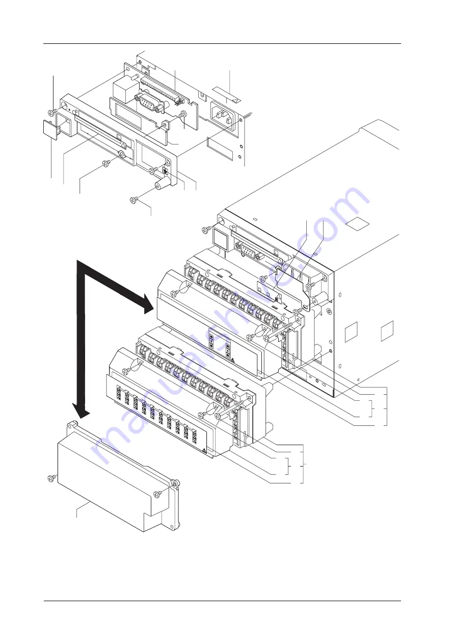
Страница 31: ...SM 04L01A01 01E 7 6 16 17 18 25 19 20 23 24 26 21 22 7 15 14 1 2 3 6 5 4 11 12 13 10 9 8 7 1 DX100 Customer Maintenance Parts List...
Страница 32: ...Bracket not C2 C3 CF1 RS 232 Bracket C2 Tapping Screw not C3 CF1 B H Screw M3x8 Terminal Option Terminal Assembly 2 Option Terminal Assembly 9 15 Option Terminal Assembly 3 Option Terminal Assembly 10...
Страница 33: ...tandard 1 2 Part No A1006WD Item 1 2 Description 1 A1253JZ 1 3P 2P Adapter 1 1 A1009WD 3 4 5 8 A1023WD A1024WD A1352EF 1 1 Power Supply Code GB standard 6 6 A1064WD 1 1 Fuse P1 B9968MZ 1 CD ROM for Ma...
Страница 34: ...Copyright Oct 1999 YK 13th Edition Oct 2009 YK CMPL DX200 01E Note Parts marked with a symbol are Customer Maintenance Parts CMP The contents of this CMPL are subject to change without prior notice a...
Страница 35: ...g Plate DX210 220 230 B H Screw M4x12 Fuse not P1 Bezel Assembly 1 1 4 4 1 1 1 3 1 1 B9968AX B9968AK B9968AT B9968AM B9968AP B9968AN Y9412LB A1423EF Fuse P1 1 A1463EF B9968BE 8 7 6 5 4 3 2 Qty Part No...
Страница 36: ...E 7 11 7 CUSTOMER MAINTENANCE PARTS LIST 10 9 8 16 17 35 31 32 33 30 34 39 38 37 36 26 1 2 7 6 5 4 3 11 14 13 12 15 29 28 27 25 24 23 22 21 20 19 18 40 41 42 43 44 45 46 47 7 3 DX200 Customer Maintena...
Страница 37: ...sembly DX230 N1or N2 10ch Scanner Assembly DX230 not N1 N2 Slow AD PT Assembly DX230 not N1 10ch ISO Scanner Assembly DX220 230 N1or N2 10ch Scanner Assembly DX220 230 not N1 N2 4ch Scanner Assembly D...
Страница 38: ...ezel Assembly for English Description 1 B9968BE 1 2 B9968BB 1 Sub Bezel Assembly B9968PA Back Light Unit KYOCERA Key Case Assembly for English Key Case Assembly for Japanese Front Plate 1 1 1 1 A1048V...
Страница 39: ...7 14 44 43 16 17 18 15 14 13 6 10 11 12 9 8 7 4 5 3 2 1 58 31 35 32 34 33 25 30 29 26 28 27 19 24 23 20 22 21 52 53 54 57 48 55 56 45 46 47 51 50 49 36 37 42 41 38 40 39 60 7 3 DX200 Customer Mainten...
Страница 40: ...30 29 B9968DJ 2 Screw Screw 2 B9900SG 28 27 B9968DG 1 Cover Cover Assembly 1 B9968DF 26 Option Terminal Assembly 4 5 9 10 1 B9968KF 25 Name Plate 17 20 21 1 B9968FN Name Plate 6 9 10 1 B9968FM Name P...
Страница 41: ...8 A1023WD A1064WD A1423EF 1 1 Power Supply Code SAA standard 5 5 A1024WD 1 1 Fuse not P1 Manuals Bracket Assembly not H5 1 2 B9900BX CD ROM for Manuals 1 B9968MZ 9 select 5 DX2 H5R 6 DX2 H5H 7 E9655FX...