Yingli Solar PV Modules, Installation and User Manual
page 5
Landscape Orientation
Portrait Orientation
this information).
Mounting structures and other mechanical parts must be designed and approved
to withstand the design wind and snow loads applicable for a particular site.
Yingli Solar PV modules must not be subjected to forces from the substructure,
including forces caused by thermal expansion.
The mounting method must not result in the direct contact of dissimilar
metals with the aluminum frame of the PV module that will result in galvanic
corrosion. An addendum to UL Standard 1703 “Flat Plate Photovoltaic Modules
and Panels” recommends metal combinations not exceed an electrochemical
potential difference of 0.5 Volts.
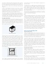
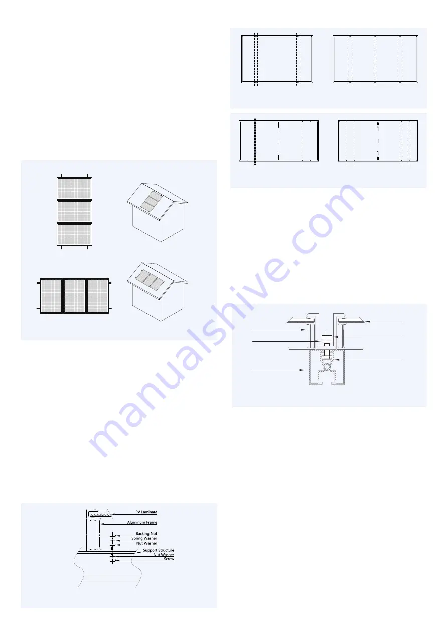
Yingli Solar PV modules can be mounted in landscape or portrait orientation, as
illustrated in Figure 10, provided that the mounting method follows one of the
acceptable methods listed below.
Figure 10: Landscape and portrait mounting
In order to maintain the fire class rating, the distance between the PV module
front surface (glass) and the roof surface shall be at least 10 cm. This spacing
also allows air flow to cool the PV module. Install PV modules with a minimum
spacing of 1 cm between neighboring frames to allow for thermal expansion.
Mounting Methods
The following mounting methods are available:
Bolts or Clamps
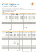
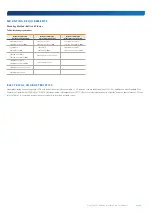
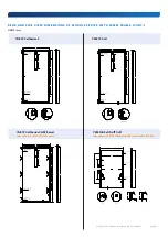
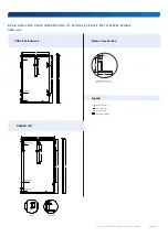
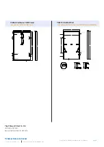
Refer to the Module Supplement distributed with this manual to determine how
many connection points are required for a specific module series. The locations
of mounting holes and clamp tolerances are illustrated in the drawings located
in the Module Supplement. Do not modify the existing mounting holes or drill
new holes. Do not apply excessive pressure on the frame such that the frame
deforms.
•
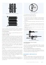
Bolts:
Modules must be mounted using the mounting holes located on the rear
side of the long frame parts using M8 stainless steel bolts, nuts, and washers.
The torque of screw tightening should between 14N∙m to 20N∙m.
Figure 11: Detail of a bolt mounting attachment
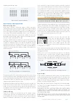
Figure 12-1 : Mounting rails must run perpendicularly to the long frame
(60 or 72 cell modules)
Figure 12-2 : Mounting rails must run perpendicularly to the long frame
(120 or 144cell modules)
•
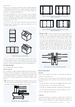
Top-down Clamps:
Third-party clamps that have been designed for PV
mounting structures are an approved mounting attachment method for
Yingli Solar PV modules. Modules must be fastened using clamps applied
to the top side of the long frame parts. A clamp holds two modules except
for the clamps at the beginning and end of a module row. The centerline of
the clamps must be in line with the mounting hole positions plus or minus
a distance of 50mm. The module clamps should not contact with the front
glass and deform the frame. and avoiding shadowing effects from the module
clamps. The module frame is not to be modified under any circumstances.
The applied torque value should be big enough to fix the modules
steadily,The torque of screw tightening should between 16N∙m to 24N∙m.
Figure 13: Detail of a top-down clamp mounting attachment
M A I N T E N A N C E
General
Yingli Solar recommends that PV systems be periodically inspected by the
installer, or other qualified person.
The purpose of the PV system inspection is to ensure that all system components
are functioning properly. At a minimum, this inspection should confirm the
following:
– All cables and connector attachments are undamaged and properly secured
– No sharp objects are in contact with the PV module surfaces
– PV modules are not shaded by unwanted obstacles and/or foreign material
– Mounting and grounding components are tightly secured with no corrosion
Defects should be addressed immediately.
Cleaning
Over time, dirt and dust can accumulate on the glass surface of the module,
reducing its power output. Yingli Solar recommends periodic cleaning of PV
modules to ensure maximum power output, especially in regions with low
Screw
Backing Nut
Nut Washer
PV Laminate
Mounting Rail
Aluminum Frame


