background image


*** Great care must be taken to ensure 

that  no  oil  enters  the  Yazaki  chiller-
heater!    Permanent  damage  could  result 
from  even  a  small  amount  of  oil  being 
introduced into the vacuum section! *** 


Never

  leave  a  vacuum  pump  running 

unattended.    Power  loss  could  allow  the 
chiller-heater  vacuum  section  to  suck  oil 
out of the pump in a matter of seconds. 


Never

  have  the  Service  Valve  open 

unless  the  vacuum  pump  is  running  and 
the  integrity  of  the  vacuum  lines  between 
the valve and the pump has been verified 
as tight. 


Never

  have  the  vacuum  pump  discharge 

tube  in  the  water  bucket  unless  the 
vacuum  pump  is  running.    The  vacuum 
pump  could  suck  water  from  the  bucket 
and contaminate the oil charge. 


Never


pull 

an 

extended 

vacuum 

(exceeding  a  few  hours)

.    If  such  seems  to 

be  necessary,  there  is  likely  to  be 
something  wrong  with  the  vacuum  pump 
or  the  oil  has  been  contaminated  with 
moisture  inherently  found  inside  the 
chiller-heater vacuum section. 


Always

 start with a fresh oil charge in the 

vacuum pump. 


Always

  use  a  liquid  trap  or  collection 

flask. 


Always

 use a vacuum gauge to verify the 

level  of  vacuum  achieved.    Run  time  has 
almost  nothing  to  do  with  the  level  of 
vacuum achieved. 

Use  only  dual-stage,  deep  vacuum 

pumps.  Typical refrigeration vacuum pumps 

may not perform well on a vessel as large as 
the  chiller-heater

’s  vacuum  section.    Just 

because  the  vacuum  pump  has  stopped 
producing  bubbles  in  the  water  bucket  does 
NOT mean the vacuum level is adequate.  A 
digital  vacuum  gauge  MUST  be  used  in 
order  to  determine  the  true  level  of  vacuum 
achieved. 

The  desired  level  of  vacuum  on  a 

machine  that  is  not  running  would  be  less 
than  2000  microns 

(<2  mmHg)

,  with  less  than 

1000  microns 

(<1  mmHg)

  preferred.    On  a 

machine  actively  running  in  Cool  mode 

(currently  attempting  to  satisfy  chilled  water  loop 
load)

,  the  desired  level  of  vacuum  is  4000-

5000 microns 

(4-5 mmHg)

, no less.  Any lower 

than  that  on  a  running  machine  can  cause 
the 

vacuum 

pump 

to 

remove 

an 

extraordinary  amount  of  refrigerant  vapor 

(water)

step-by-step, 

detailed 

evacuation 

method  is  provided  in  the  Service  Manual.  
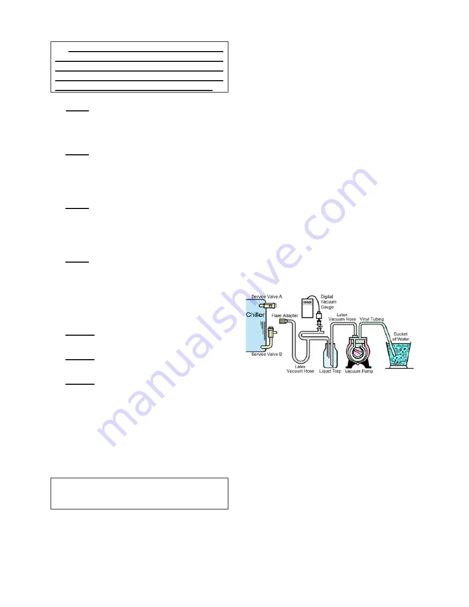
The  general  evacuation  assembly  setup  is 
displayed in Figure 9. 


Figure 9 

– GENERAL EVACUATION 

ASSEMBLY SETUP 


CHEMICAL MAINTENANCE


It  is  not  necessary  to  perform  regular 

chemical  maintenance  on  the  Yazaki 
chiller-heater itself. 


The 

chemical 

balance 

has 

been 

established  in  the factory  during  run testing.  
Normally,  the  only  chemical  that  must  be 
maintained  is  the  inhibitor  charge.    By 
capturing 

non-condensable 

gases, 

comparisons  can  be  made  to  determine  if 
the  normal  hydrogen  byproduct  is  being 
produced  at  anticipated  rates.    If  more 
hydrogen is being produced than anticipated, 
a maintenance inhibitor charge may need to 
be  introduced  into the  machine  by  the  ASP.  
An inhibitor charge is typically needed every 
three 

(3) 

years  in  Yazaki  gas-fired  chiller-

heaters. 

Содержание CH-K100

Страница 1: ...UCTIONS and properly maintained it can provide many years of trouble free operation CONTENTS GENERAL Page ABSORPTION PRINCIPLE 2 COOLING OPERATION 2 HEATING OPERATION 3 CONTROLS GENERAL INFORMATION 4...

Страница 2: ...cooled and heat is normally rejected to a cooling tower though ground loop is also an option COOLING OPERATION High Temperature Generator HGE The gas burner heats a dilute lithium bromide solution in...

Страница 3: ...nd semi concentrated solution flow into the primary separator in exactly the same manner as in the cooling cycle Low Temperature Generator LGE In Heat mode the changeover valve opens a path for the se...

Страница 4: ...y also be supervised and controlled by external control systems to a limited degree when the necessary interconnections are installed Additional controls and interlocks can be explained by your ASP On...

Страница 5: ...2 10 Rated 300vac F4 2 Fuji Model FGAO 2 Rated 250vac F11 F12 2 Fuji Model FGAO 2 Rated 250vac F31 F32 1 Fuji Model FGAO 2 Rated 250vac FB11 FB12 2 Fuji Model FGAO 2 Rated 250vac FB21 FB22 15 Nagasaw...

Страница 6: ...on the I O Board to ON The leaving chilled water temperature can be adjusted using the TC potentiometer on the CPU Board The leaving chilled water set point can be set in a range of 40 1 F 4 5 C to 59...

Страница 7: ...ress the alarm RESET button to restart the cooling or heating operation If Error Code 52 is amongst the codes being displayed it will also be necessary to press the RESET button on the burner controll...

Страница 8: ...Gas Pressure Check Supply and Manifold Inhibitor Check If required For the K Series an inhibitor charge is needed every 3 years on average Palladium Cell Heater Check Flow Rate Check Solution Pump Rot...

Страница 9: ...s vacuum section Just because the vacuum pump has stopped producing bubbles in the water bucket does NOT mean the vacuum level is adequate A digital vacuum gauge MUST be used in order to determine the...

Страница 10: ...iller heater itself as well If doing so pressurize the unit to the same pressure as the circuits using nitrogen See the Service Manual for further details TROUBLESHOOTING SYMPTOM Chiller heater does n...

Страница 11: ...iption Notes Reset Type FS Flow switch alarm Chilled hot water flow switch FS1 open but for less than 10 minutes After 10 minutes this changes automatically to error code 27 Auto 01 DCP power error Op...

Страница 12: ...10 C or above 212 F 100 C Ignored for first 10 minutes of P2 operation Manual 36 CND sensor error CND sensor reads below 14 F 10 C or above 212 F 100 C Auto 40 Loss of cooling capacity LT temperature...

Страница 13: ...13 Please send a copy of any maintenance data sheets to Yazaki Energy Systems Inc at the address FAX number and or email address listed on the last page of this document...

Страница 14: ...Labor Charges for warranty service can be obtained by an authorized service provider upon written request to YESI 7 LIMITATION OF WARRANTY AND LIMITATION OF REMEDY CUSTOMER s remedies shall be limite...

Страница 15: ......

Страница 16: ...MS INC 701 E PLANO PKWY SUITE 305 PLANO TEXAS 75074 6700 Phone 469 229 5443 Fax 469 229 5448 Email yazaki yazakienergy com Web http www yazakienergy com This symbol on the product s name plate means i...

Отзывы: