
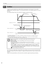


3.1 Outline
3.1.3 I/O Signal Connector (CN1) Pin Arrangement
3-4
3.1.3
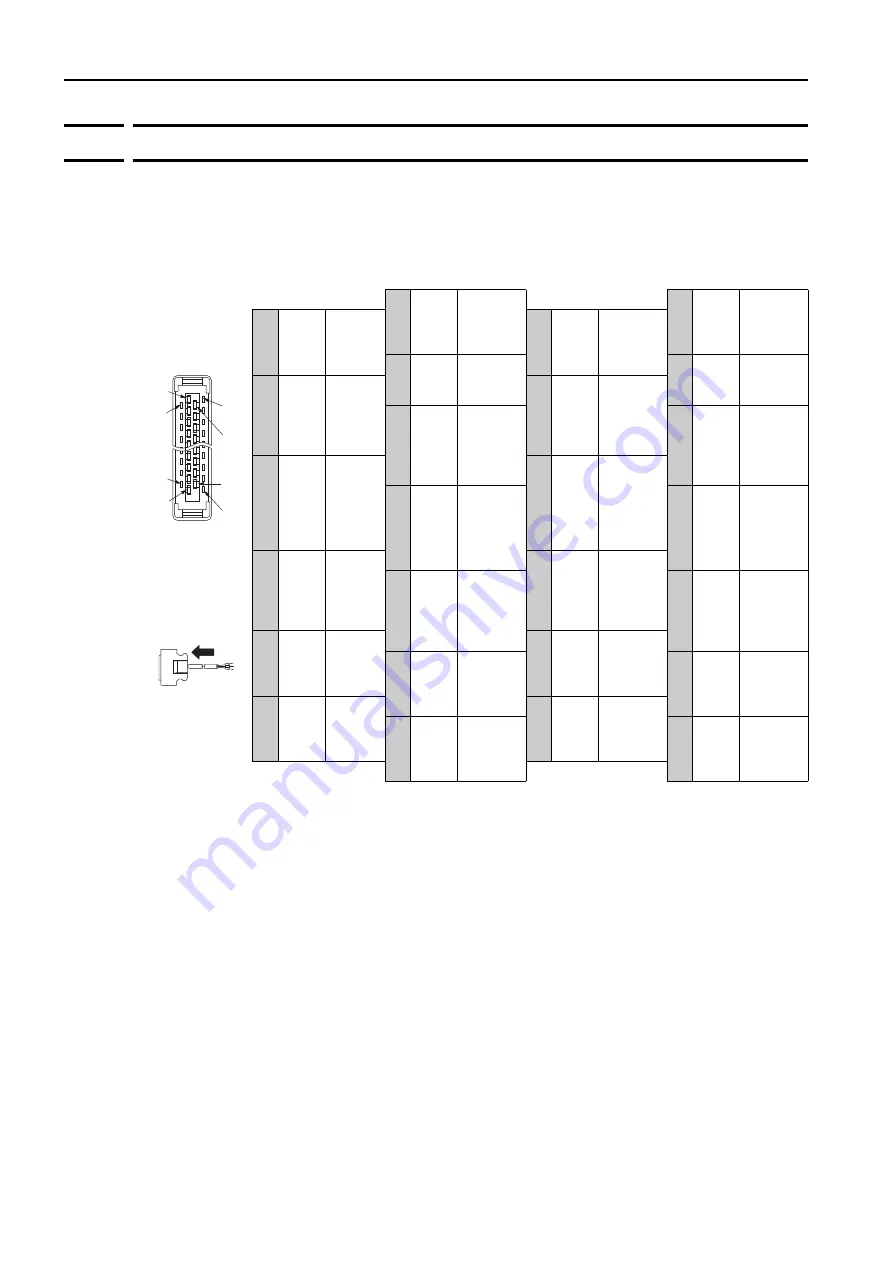
I/O Signal Connector (CN1) Pin Arrangement
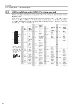
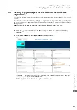
The following figure gives the pin arrangement of the of the I/O signal connector (CN1) for the
default settings.
When you use line-driver high-speed outputs, wire the outputs to CN1-17 and CN1-18 and to
CN1-21 and CN1-22. When you use photocoupler normal outputs, allocate the output signals
for triggers at preset positions as normal and wire the outputs to CN1-1 and CN1-2, CN1-23
and CN1-24, or CN1-25 and CN1-26.
The above view is
from the direction
of the following
arrow without the
connector shell
attached.
1
/SO1+
(/BK+)
General-
Purpose
Sequence
Output 1
14 BAT+
Battery for
Absolute
Encoder (+)
2
/SO1-
(/BK-)
General-
Purpose
Sequence
Output 1
15 BAT-
Battery for
Absolute
Encoder (-)
3
ALM+
Servo
Alarm
Output
16 SG
Signal
Ground
4
ALM-
Servo
Alarm
Output
17 HSO1
High-
Speed
Preset
Position
Output 1
5
TH
Linear
Servomotor
Overheat
Protection
Input
18 /HSO1
High-
Speed
Preset
Position
Output 1
6
+24VIN
Sequence
Input
Signal
Power
Supply
Input
19 –
–
7
/SI1
(P-OT)
General-
Purpose
Sequence
Input 1
20 –
–
8
/SI2
(N-OT)
General-
Purpose
Sequence
Input 2
21 HSO2
High-
Speed
Preset
Position
Output 2
9
/SI3
(/DEC)
General-
Purpose
Sequence
Input 3
22 /HSO2
High-
Speed
Preset
Position
Output 2
10
/SI4
(/EXT1)
General-
Purpose
Sequence
Input 4
23 /SO2+
General-
Purpose
Sequence
Output 2
11
/SI5
(/EXT2)
General-
Purpose
Sequence
Input 5
24 /SO2-
General-
Purpose
Sequence
Output 2
12
/SI6
(/EXT3)
General-
Purpose
Sequence
Input 6
25 /SO3+
General-
Purpose
Sequence
Output 3
13 /SI0
General-
Purpose
Sequence
Input 0
26 /SO3-
General-
Purpose
Sequence
Output 3
Pin 14
Pin 25
Pin 26
Pin 1
3
Pin 12
Pin 2
Pin 1
Pin 15