


YASKAWA
SIEP C730600 0E YAI Modbus TCP/IP Technical Manual
35
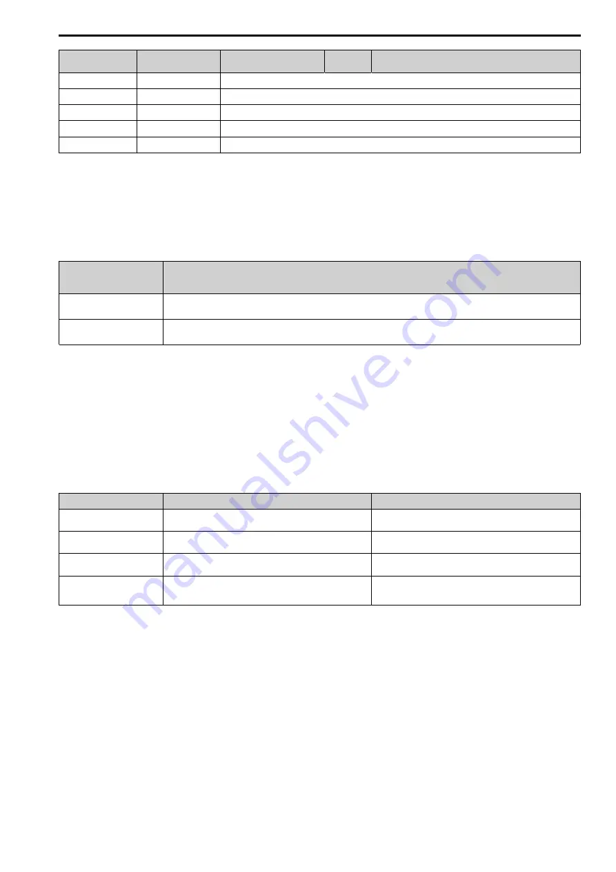
No. (Modbus
Register)
Drive Registers
Register Name
Bit
Description
200C
4E
Terminal A1 Input Level Monitor (U1-13)
200D
49
Digital Input Terminal Status (U1-10)
200E
50
Terminal A3 Input Level Monitor (U1-15)
200F
F1
PG Count Channel 2
2010
4D
Drive Software Number (Flash) (U1-25)
■
Types of Enter Commands
The drive supports the two Enter commands shown in
An Enter command is enabled by writing 0 to register number 0900 (Hex.) or 0910 (Hex.).
These registers can be written to only.
An error will occur if the user attempts to read from these registers.
Table 7.4 Types of Enter Commands
Register Number
(Hex.)
Description
0900
When you write parameter data to the EEPROM, you will enable the data on the RAM at the same time.
Parameter changes remain even if the power supply is cycled.
0910
This updates the data on the RAM, but does not write data to the EEPROM.
Parameter changes are lost when the drive is shut off.
Note:
•
You can write the EEPROM to the drive a maximum of 100,000 times. Do not frequently execute the Enter command (0900 (Hex.))
that is written to EEPROM. When the command data or broadcast message is transmitted to the drive, the Enter command is not
necessary.
•
Parameter data cannot be written to EEPROM during undervoltage, even using 0900 (Hex.).
•
If undervoltage occurs when a making several parameter changes issued with a single ENTER command, the writing process may be
aborted before all of the new changes have been written. Because all of the data has not yet been written, the EEPROM data error
CPF06
will be displayed the next time power to the drive is cycled. To prevent
CPF06
, wait approximately 5 seconds after issuing the
ENTER command before shutting off drive power.
■
Enter Command Function Differences Depending on the Setting of H5-11
Table 7.5 Enter Command Function Differences Depending on the Setting of H5-11
H5-11 Settings
H5-11 = 0
H5-11 = 1
Time when the parameter settings
are enabled
When the drive receives the Enter command from the master
When you change the parameter settings
Upper and lower limit check
Checks the upper and lower limits and considers the related parameter
settings.
Checks the upper and lower limit of the changed parameter only.
Default setting of related
parameters
Not affected. The settings of related parameters remain unchanged.
They must be changed manually, if needed.
Automatically changes the default settings for the related parameters.
Fault detection when you set
more than one parameter
Accepts and responds as usual to correct setting data if the data
contains parameter setting errors. The drive discards the disabled
setting data, but will not return an error message.
Error occurs if only one setting is invalid. All data sent are discarded.
The drive discards the data that was sent.
■
Message Format
The data section of the Modbus packet contains the Modbus message. In this data section, the master sends
commands to the slave, and the slave responds. The message format is configured for both sending and receiving
as shown below, and the length of data packets depends on the command (function) content.
•
Unit Identifier
•
Function code
•
Data
Unit Identifier
This field is used for intra-system routing purposes. It is typically used to communicate to a or a
Modbus serial line slave through a gateway between a Modbus TCP/IP network and a Modbus serial line. This
field is set by the Modbus master in the command and must be returned with the same value in the response by the
slave. This is sometimes referred to as the Unit ID. This field is not usually used because the drive with the option
does not have a gateway function. Refer to the manual of the master or gateway used when you set the value to
the Unit identifier.