


4.5 Connecting an Absolute Encoder
Signal
Name
1CN Pin No.
Description
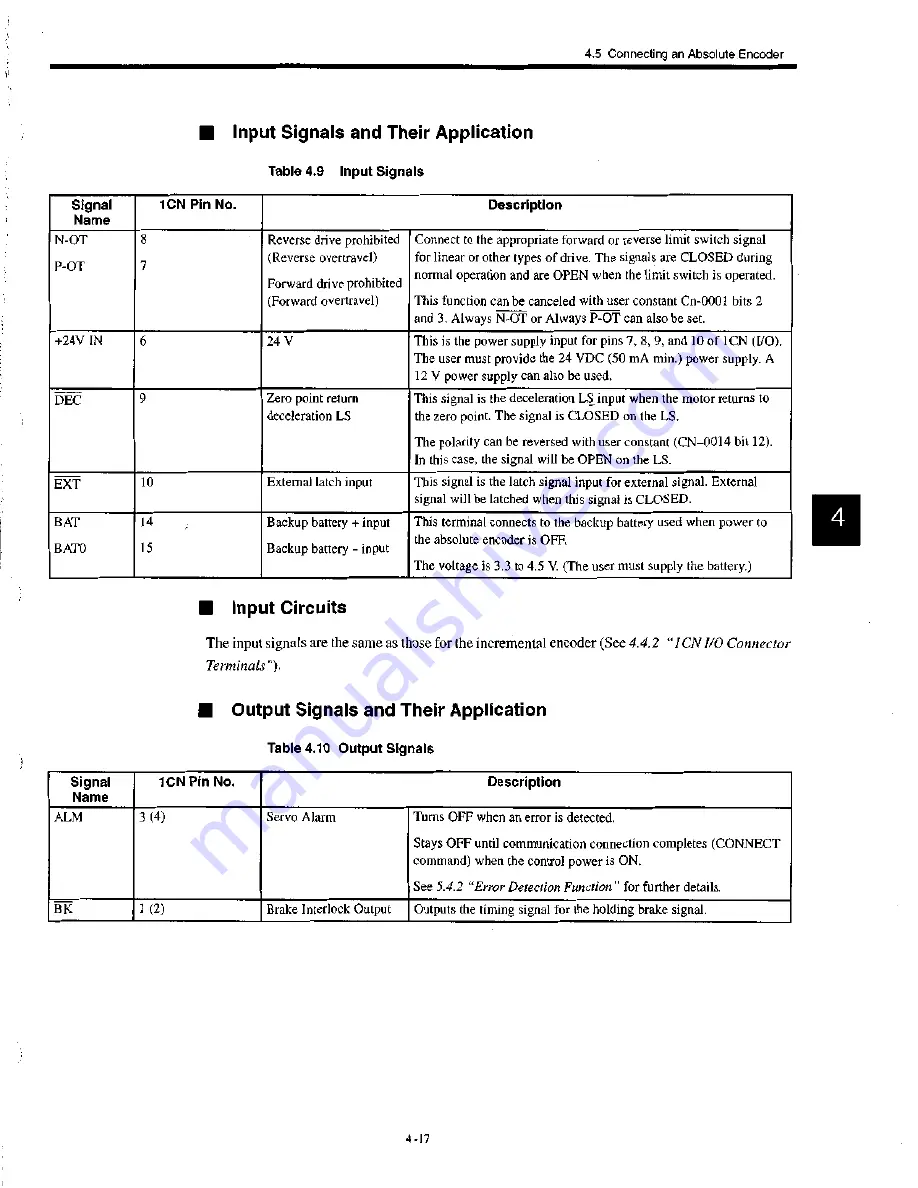
N-OT
P-OT
8
7
Reverse drive prohibited
(Reverse overtravel)
Forward drive prohibited
Connect to the appropriate forward or reverse limit switch signal
for linear or other types of drive. The signals are CLOSED during
normal operation and are OPEN when the limit switch is operated.
(Forward overtravel)
This function can be canceled with user constant Cn-0001 bits 2
and 3. Always N-OT or Always P-OT can also be set.
+24V IN
6
24 V
This is the power supply input for pins 7, 8, 9, and 10 of 1CN (I/O).
The user must provide the 24 VDC (50 mA min.) power supply. A
12 V power supply can also be used.
DEC
9
Zero point return
deceleration LS
This signal is the deceleration LS input when the motor returns to
the zero point. The signal is CLOSED on the LS.
The polarity can be reversed with user constant (CN-0014 bit 12).
In this case, the signal will be OPEN on the LS.
EXT
10
External latch input
This signal is the latch signal input for external signal. External
signal will be latched when this signal is CLOSED.
BAT
14
Backup b input
This terminal connects to the backup battery used when power to
the absolute encoder is OFF.
BATO
15
Backup battery — input
The voltage is 3.3 to 4.5 V. (The user must supply the battery.)
Signal
Name
1CN Pin No.
Description
A L M
3 (4)
Servo Alarm
Turns OFF when an error is detected.
Stays OFF until communication connection completes (CONNECT
command) when the control power is ON.
See 5.4.2 "Error Detection Function" for further details.
BK
1 (2)
Brake Interlock Output
Outputs the timing signal for the holding brake signal.
• I n p u t Signals and Their Application
Table 4.9 I n p u t Signals
II Input Circuits
The input signals are the same as those for the incremental encoder (See
4.4.2 " 1 CN I/O Connector
Terminals").
I I Output Signals and Their Application
Table 4.10 O u t p u t Signals
4 -17