


Internal cables and compressed air lines
8
-
46
•
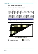
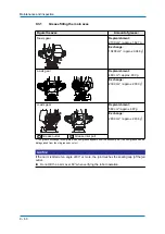
To the 3BC connection for the collision sensor on the U arm.
•
To the 3BC connection for the collision sensor on the robot controller.
Pins 7 and 8 of the respective 3BC connections on the connector plate and U arm are
connected to each other.
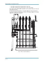
For the wiring, see the following figure, "Connecting diagram for internal connections."
The internal connections of the robot are shown in the following diagrams "Connection
diagram A" and "Connection diagram B".
Fig. 8-5: Internal connection diagram (a)
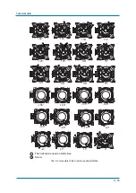
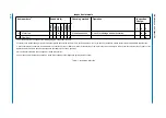
S-, L-, and U-axis with Limit Switch Specification
S-axis with Limit Switch Specification
2.
When performing the wiring of the overrun limit switch, pay attention to the color of wires.
The letters marked on the marker tubes at
parts (LB1 and LD1) are the same.
S-AXIS OVERRUN L.S.
L-AXIS OVERRUN L.S.
L
AND U-AXIS INTERFERENCE L.S.
LA1
LB1
LB2
LB2
LA2
LB1
S-AXIS OVERRUN L.S.
L-AXIS OVERRUN L.S.
L
AND U-AXIS INTERFERENCE L.S.
LC1
LD1
LD2
LD2
LC2
LD1
S-AXIS OVERRUN L.S.
LA1
LB1
LB1
S-AXIS OVERRUN L.S.
LC1
LD1
LD1
LC1
LD1
LD1
LD2
LD3
LC3
LA1
LB1
LB1
LB2
LB3
LA3
LC1
LA1
LA1
L
B1
BC2
BC1
LC2
LD2
For S-axis fan (option)
For lamp (option)
DX200
BA
T
R
KP
R
KB
A
T
0BT
P
R
R
K
K
BA
T
P
0BT
0BT
0BT
BA
T
P
6B
A
T
2
1
0BA
T
22
BA
T22
2
3
4
1
7
8
0BA
T
1
1
0BA
T
21
BA
T12
0BA
T
12
BA
T1
1
4
5
1
3
2
26
32
1
2
31
30
27
29
28
PG0V1
PG5V1
BA
T6
0BA
T
6
20
23
25
24
22
21
17
19
18
BA
T2
BA
T3
0BA
T
3
0BA
T
1
BA
T1
0BA
T
2
8
6
7
5
6
PG5V3
8
7
4
5
3
PG5V2
PG0V3
PG0V2
3
2
4
1
12
13
14
15
16
10
11
9
PG5V6
PG0V6
CN1-5
CN1-4
0V
+24V
+24V
0V
CN1-9
CN1-10
P
P
CN1-10
CN1-4
CN1-5
CN1-9
+24V
+24V
0V
0V
0V
+24V
0V
+24V
-1
-3
-2
-4
1BC(10PX4)
No.20CN
X
No,5CN
-1
-4
-3
-2
BA
T1
PG0V1
PG5V1
OBA
T
1
S
-1
No.1CN
P
P
P
PG
-6
BA
T
-10
-9
-5
-4
BA
T
OBT
OBT
+5V
0V
FG1
-2
DA
T
A-1
DA
T
A+1
S-AXIS
DA
T
A-2
DA
T
A+2
FG2
-10
BA
T
OBT
No,6CN
OBA
T
2
PG5V2
BA
T2
PG0V2
-2
-3
-4
-1
L
No.2CN
-1
-9
-6 -5
-4
-2
0V
BA
T
OBT
+5V
L-AXIS
PG
DA
T
A+3
DA
T
A-3
-2
OBA
T
3
PG0V3
PG5V3
-4
-3
BA
T3
No,7CN
-1
U
OBT
-5
-4
-9
-10
BA
T
+5V
0V
OBT
FG3
No.3CN
-1
-2
-6
BA
T
PG
U-AXIS
DA
T
A-6
DA
T
A+6
OBA
T
6
PG0V6
PG5V6
BA
T6
No,8CN
-2
-3
-4
-1
T
No.4CN
-5
-4
-9
-10
-1
-2
-6
OBT
FG6
+5V
BA
T
0V
OBT
BA
T
T
-AXIS
PG
CN1-1
SPG+1
CN1-2
SPG-1
P
CN1-1
CN1-2
SPG-1
SPG+1
CN1-3
FG1
CN1-3
FG1
CN1-8
FG2
CN1-7
CN1-6
SPG-2
SPG+2
CN1-8
FG2
CN1-7
CN1-6
P
SPG-2
SPG+2
CN2-3
CN2-2
CN2-1
SPG-3
SPG+3
FG3
CN2-3
CN2-2
CN2-1
P
SPG-3
SPG+3
FG3
CN3-8
CN3-7
CN3-6
SPG-6
SPG+6
FG6
CN3-8
CN3-7
CN3-6
P
SPG-6
SPG+6
FG6
LB1
+24V
E
BC2
AL2
CN4-1
CN4-6
CN4-8
CN4-3
LB1
+24V
BC2
AL2
CN4-6
CN4-1
E
CN4-3
CN4-8
AL1
CN4-7
CN4-7
P
P
AL1
CN4-10
0V
CN4-10
LA2
LB2
LC2
LD2
LA2
LB2
LD1
LD2
LB1
LB2
LA3
LB3
LC3
LD3
LB2
LB1
LD2
LD1
CN2-10
CN2-10
+24V
CN4-4
+24V
CN2-4
LD1
CN4-5
P
CN2-5
LD1
LC1
L
D1
+24V
+24V
A1
Connected to
A1
Connected to
B1
Connected to
A2
Connected to
B2
Connected to
A3
Connected to
B3
Connected to
B1
Connected to
P
P
P
P
P
P
P
P
P
E
2
1
2
1
BASE
A2
B2
A3
B3
A1
B1
AL1
AC1
AL2
AC2
S
FA
N
1. For the limit switch specification, the connection of the section
Notes
A
B
and parts are changed as follows:
Содержание MPL500-J00
Страница 1: ...ROBOTICS MPL500 J00 YR MPL0500 J00 Operating and Maintenance Manual ...
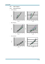
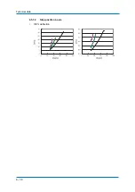
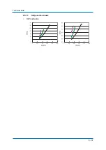
Страница 36: ...Technical data 6 36 6 5 1 2 Stop position L axis 100 deflection ...
Страница 37: ...Technical data 6 37 6 5 1 3 Stop position U axis 100 deflection ...
Страница 61: ...Maintenance and inspection 9 61 Air outlet cap Joint 80 9 0 170 1 1 2 2 2 1 2 ...


