background image

2

Transport

2.1

Transport Method

2-2

HW1483028

HW1483028

2.1.1 Using a Crane 

As a rule, the manipulator should be lifted by a crane with a four-leg 
brindle sling using the attached eyebolts when removing it from the 
package and moving it. 

 Be sure that the manipulator is fixed with the shipping bolts and brackets 
before transport, and lift it in the posture as shown in 

fig. 2-1  

“Transporting Position” 

.

Fig. 2-1: Transporting Position

M6×16

M6×16

Shipping bracket

Hexagon socket 

head cap screw M20 
(12 screws)

Delivered with the manipulator

Rubber plate

Rubber plate

0

0

0゚

0゚

-77゚

-90゚

T

B

R

U

L

S

-144384

-123529

0゚

0

0゚
0

Factory setting for angle and pulse of each axis

Axis

Angle

Pulse

13/69

Содержание MOTOMAN-MC2000 II

Страница 1: ...initial operation read these instructions thoroughly and retain for future reference MOTOMAN INSTRUCTIONS MOTOMAN MC2000 II INSTRUCTIONS DX200 INSTRUCTIONS DX200 OPERATOR S MANUAL for each purpose DX...

Страница 2: ...CAUTION Some drawings in this manual are shown with the protective covers or shields removed for clarity Be sure all covers and shields are replaced before operating this product The drawings and pho...

Страница 3: ...Indicates a potentially hazardous situation which if not avoided could result in minor or moderate injury to personnel and damage to equipment It may also be used to alert against unsafe practices MAN...

Страница 4: ...Be sure to use a lockout device to the safeguarding when going inside Also display the sign that the operation is being performed inside the safeguarding and make sure no one closes the safeguarding V...

Страница 5: ...to conducting manipulator teaching If problems are found repair them immediately and be sure that all other necessary processing has been performed Check for problems in manipulator movement Check fo...

Страница 6: ...so an identification label with important information is placed on the body of the manipulator Prior to operating the manipulator confirm the contents Fig Warning Label Locations WARNING Do not enter...

Страница 7: ...4 3 4 Protection Class 3 4 3 5 Location 3 4 4 Wiring 4 1 4 1 Grounding 4 1 4 2 Cable Connection 4 2 4 2 1 Connection to the Manipulator 4 2 4 2 2 Connection to the DX200 4 2 5 Basic Specifications 5 1...

Страница 8: ...Exchange Procedures 9 7 9 3 2 Grease Replenishment Exchange for S axis Speed Reducer 9 8 9 3 2 1 Grease Replenishment 9 8 9 3 2 2 Grease Exchange 9 9 9 3 3 Grease Replenishment Exchange for L axis Sp...

Страница 9: ...Contents ix HW1483028 HW1483028 11 1 S Axis Unit 11 1 11 2 L Axis Unit 11 3 11 3 URBT Axis Unit 11 5 11 4 U Arm Unit 11 7 11 5 Wrist Unit 11 9 9 69...

Страница 10: ...r items Information for the content of optional goods is given separately Manipulator DX200 Programing Pendant Manipulator Cable between the DX200 and the Manipulator x 2 CAUTION Confirm that the mani...

Страница 11: ...manipulator corresponds to the DX200 The order number is located on a label as shown below Fig 1 1 Location of Order Number Labels THE MANIPULATOR AND THE CONTROLLER SHOULD HAVE SAME ORDER NUMBER ORDE...

Страница 12: ...affect performance NOTE Check that the eyebolts are securely fastened The weight of the manipulator is approximately 925 kg including the shipping bolts and brackets Use a wire rope strong enough to...

Страница 13: ...sure that the manipulator is fixed with the shipping bolts and brackets before transport and lift it in the posture as shown in fig 2 1 Transporting Position Fig 2 1 Transporting Position M6 16 M6 16...

Страница 14: ...nsert claws under the pallet and lift it The pallet must be strong enough to support the manipulator Transport the manipulator slowly with due caution in order to avoid overturning or slippage Fig 2 2...

Страница 15: ...sition Fig 2 3 Shipping Bolts and Brackets The A shipping brackets are painted in yellow Position Bolt Type Pcs A Hexagon socket head cap screw M20 X 70 mm Tensile strength 1200 N mm2 or more 12 NOTE...

Страница 16: ...e to observe this warning may result in injury or damage Do not start the manipulator or even turn ON the power before it is firmly anchored The manipulator may overturn and cause injury or damage CAU...

Страница 17: ...unting Procedures for Manipulator Base The manipulator should be firmly mounted on a baseplate or foundation strong enough to support the manipulator and withstand repulsion forces during acceleration...

Страница 18: ...r size The manipulator base is tapped for eight mounting holes securely fix the manipulator base to the baseplate with hexagon head screws M20 70 mm long is recommended Next fix the manipulator base t...

Страница 19: ...rms to IP54 the wrist part conforms to IP67 3 5 Location When installing a manipulator it is necessary to satisfy the following environmental conditions Ambient Temperature 0 to 45 C Humidity 20 to 80...

Страница 20: ...e primary power supply off and put up a warning sign ex DO NOT TURN THE POWER ON Failure to observe this warning may result in fire or electric shock CAUTION Wiring must be performed by authorized or...

Страница 21: ...oth manipulator cables and the connectors on the connector base of the manipulator When connecting adjust the cable connector positions to the main key positions of the manipulator and insert cables i...

Страница 22: ...4 2 Cable Connection 4 3 HW1483028 HW1483028 Fig 4 3 a Manipulator Cable Connectors Manipulator Side Fig 4 3 b Manipulator Cable Connectors DX200 Side A ViewA Maniplator back view 2BC AIR S1 1BC X21 X...

Страница 23: ...T Axis 4 36 rad s 250 s Allowable Moment4 4 Refer to table chapter 6 1 Allowable Wrist Load for details on the permissible moment of inertia R Axis 110 N m 11 kgf m B Axis 110 N m 11 kgf m T Axis 55N...

Страница 24: ...art Names and Working Axes 5 3 Baseplate Dimensions Fig 5 2 Baseplate Dimensions T T B B U L L S S U R R Wrist Wrist flange L arm Rotary head Manipulator base U arm S head Lower arm Upper arm View A 4...

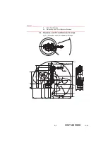
Страница 25: ...5 4 Dimensions and P Point Maximum Envelope Fig 5 3 Dimensions and P Point Maximum Envelope 180 180 R2038 R778 330 800 175 2388 1103 288 0 479 776 368 203 304 368 290 2038 778 561 306 183 0 290 637 13...

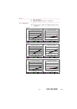
Страница 26: ...axis measured under the standard of ISO10218 5 5 1 Stop Category 0 Stopping Angles and Times 5 5 1 1 Position 100 Fig 5 4 Stop Category 0 Position 100 Stopping Angle and Time for each Axis a S Axis b...

Страница 27: ...5 5 1 2 Position 66 Fig 5 5 Stop Category 0 Position 66 Stopping Angle and Time for each Axis a S Axis b L Axis b U Axis Stop Category 0 Position 66 Stop Category 0 Position 66 Stop Category 0 Positi...

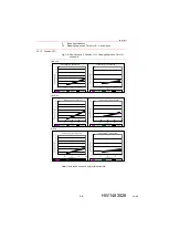
Страница 28: ...5 6 Stop Category 0 Position 33 Stopping Angle and Time for each Axis Note U axis takes one pose only for this structure a S Axis b L Axis U Axis Stop Category 0 Position 33 Stop Category 0 Position 3...

Страница 29: ...r each Axis NOTE Stopping angles and times at Stop category 1 are not subjected to the load of the manipulator a S Axis Notes Not depends on the load b L Axis Notes Not depends on the load c U Axis No...

Страница 30: ...of the S axis can be altered in accordance with the operating conditions as shown in table 5 2 S Axis Operating Range If alteration is necessary contact your Yaskawa representative in advance Table 5...

Страница 31: ...hown in fig 6 1 Moment Arm Rating The allowable total moment of inertia is calculated when the moment is at the maximum Contact your Yaskawa representative beforehand when only moment of inertia or lo...

Страница 32: ...the attachment be mounted inside the fitting Fitting depth of inside and outside fittings must be 5 mm or less Fig 6 2 Wrist Flange P C D 80 42 40 6 8 Unit mm Tapped hole M8 Alignment mark 6 dia 0 01...

Страница 33: ...g conditions should be observed to attach or install peripheral equipment Fig 7 1 Installing Peripheral Equipment 122 100 50 210 240 20 10 180 11 5 122 120 50 50 A Tapped hole M8 4 holes pitch 1 25 de...

Страница 34: ...e allowable current for internal user I O wiring harness 5 1 A or less for each wire The total current value for pins 1 to 23 must be 34 5A or less The maximum pressure for the air line 490 kPa 5 kgf...

Страница 35: ...activated the power supply to the manipulator is interrupted then the manipulator makes an emergency stop as a result Refer to 8 9 Overrun Tool Shock Sensor Releasing in DX200 INSTRUCTIONS for releas...

Страница 36: ...BAT FG6 5V OBT 0V BAT 10 PG T AXIS No 6CN 6CN 1 FG5 BAT OBT 10 DATA 6 5CN 1 5V OBT BAT 0V 2 DATA 5 DATA 5 5V 0V FG4 BAT OBT 10 No 4CN 4CN 1 BAT OBT 2 DATA 4 DATA 4 PG B AXIS PG R AXIS OBT 5V OBT FG3 0...

Страница 37: ...5 C 7 C 9 C 11 B 12 C 8 C 2 C 4 C 6 B 11 C 5 E 2 E 7 E 8 E 5 E 6 E 1 B 5 E 3 E 4 B 10 F 2 F 7 F 8 F 5 F 6 F 1 B 4 F 3 F 4 D 4 D 7 D 8 D 5 D 6 D 3 B 3 D 1 D 2 A 1 A 3 A 6 B 9 B 2 A 5 C 7 C 9 C 11 B 12...

Страница 38: ...ormed by specified personnel Failure to observe this caution may result in electric shock or injury For disassembly or repair contact your Yaskawa representative Do not remove the motor and do not rel...

Страница 39: ...n loose bolts Replace if necessary 6 Cover mounting screws Screwdriver Wrench Tighten loose bolts Replace if necessary 7 S L U R B T axes motor connector Manual Tighten loose bolts 8 Connector base Ma...

Страница 40: ...akage indicates the possibility that grease has seeped into the motor This can cause a motor breakdown Contact your Yaskawa representative 3 When checking for conduction with multimeter connect the ba...

Страница 41: ...pection Items 7 2 S axis Optional 6 10 4 6 7 S axis S axis L axis Optional U axis Optional U axis B axis T axis T axis R axis 10 9 4 4 7 4 2 L axis L axis L axis U axis U axis R B axes T axis B axis R...

Страница 42: ...n shown in fig 9 2 Battery Location Battery Type HW0470360 A Fig 9 2 Battery Location Fig 9 3 Battery Connection 2BC AIR S1 1BC Connector base Cross head APS bolt M6 Length 12 6 bolts Cross head APS b...

Страница 43: ...the new one 3 Remove the battery pack from the battery holder 4 Connect the new battery pack to the unoccupied connectors on the board 5 Remove the old battery pack from the board 6 Mount the new bat...

Страница 44: ...lug screw from the grease exhaust port the grease will leak inside a motor or an oil seal of a speed reducer will come off which may result in damage to the motor Make sure to remove the plug screw Do...

Страница 45: ...few minutes to discharge the excess grease 5 Wipe the discharged grease with a cloth and reinstall the hexagon socket head plug PT3 8 to the exhaust port Before installing the plug apply Three Bond 1...

Страница 46: ...a few minutes to discharge the excess grease 6 Wipe the discharged grease with a cloth and reinstall the hexagon socket head plug PT3 8 to the exhaust port Before installing the plug apply Three Bond...

Страница 47: ...ess 6 Move the L axis for a few minutes to discharge the excess grease 7 Wipe the discharged grease with a cloth and reinstall the hexagon socket head plug PT3 8 to the exhaust port Before installing...

Страница 48: ...is for a few minutes to discharge the excess grease 8 Wipe the discharged grease with a cloth and reinstall the hexagon socket head plug PT3 8 to the exhaust port Before installing the plugs apply Thr...

Страница 49: ...grease zerk is delivered with the manipulator 5 Inject grease through the grease inlet using a grease gun Grease type Molywhite RE No 00 Amount of grease 390 cc 780 cc for 1st supply Air supply pressu...

Страница 50: ...ease approx 1950 cc Air supply pressure of grease pump 0 3 MPa or less Grease injection rate 8 g s or less 6 The grease discharge is complete when new grease appears from the exhaust port The new grea...

Страница 51: ...n be distinguished from the old grease by color 5 Move the R axes for a few minutes to discharge the excess grease 6 Wipe the discharged grease with a cloth and reinstall the hexagon socket head plug...

Страница 52: ...a few minutes to discharge the excess grease 7 Wipe the discharged grease with a cloth and reinstall the hexagon socket head plug PT3 8 to the exhaust port Before installing the plug apply Three Bond...

Страница 53: ...grease by color 5 Move the B axes for a few minutes to discharge the excess grease 6 Wipe the discharged grease with a cloth and reinstall the hexagon socket head plug PT1 8 to the exhaust port Befor...

Страница 54: ...es for a few minutes to discharge the excess grease 7 Wipe the discharged grease with a cloth and reinstall the hexagon socket head plug PT1 8 to the exhaust port Before installing the plug apply Thre...

Страница 55: ...ed at the end point of the motors BAT and OBT are marked Connect the battery packs according to the following procedure 1 Removed the cap attached to the battery backup connector of the motors 2 Conne...

Страница 56: ...s A 1 Grease Molywhite RE No 00 Yaskawa Electric Corporation 16 kg For speed reducers in each axis A 2 Liquid Gasket Three Bond 1206C Three Bond Co Ltd A 3 Battery Pack HW9470932 A Yaskawa Electric Co...

Страница 57: ...A Yaskawa Electric Corporation 1 1 C 14 R B T axes AC Servomotor SGMRV 13ANA YR2 HW0388667 A Yaskawa Electric Corporation 1 3 C 15 Internal Wire Harness HW1171927 A Yaskawa Electric Corporation 1 1 C...

Страница 58: ...1 1 HW1483028 HW1483028 11 Parts List 11 1 S Axis Unit Fig 11 1 S Axis Unit 1009 1002 1008 1012 1014 1013 1015 1011 1004 1003 1026 1027 1021 1006 1005 1022 1023 1024 1019 1020 1010 1018 1028 1029 1030...

Страница 59: ...PT3 8 STAINLESS Plug 1 1011 6310 Bearing 1 1012 HW0314016 2 Gear 1 1013 M8X85 Socket screw 1 1014 2H 8 Spring washer 1 1015 STW 50 Retaining ring C type 1 1016 HW1100190 1 S head 1 1017 TC12015014 Oil...

Страница 60: ...11 Parts List 11 2 L Axis Unit 11 3 HW1483028 HW1483028 11 2 L Axis Unit Fig 11 2 L Axis Unit 2001 2016 2010 2003 2002 2004 2006 2007 2008 2009 2018 2011 2012 2015 2017 1016 2013 2005 2019 2014 60 69...

Страница 61: ...9 E Speed reducer 1 2006 M10X40 Socket screw 18 2007 2H 10 Spring washer 18 2008 M16X45 Socket screw 6 2009 2H 16 Spring washer 6 2010 HW1301221 1 Gear 1 2011 M8X125 Socket screw 1 2012 2H 8 Spring wa...

Страница 62: ...3038 3037 3038 3037 3002 3005 3009 3001 3008 3036 3035 3006 3007 3010 3035 3013 3014 3011 3012 2002 3004 3017 3018 3015 3016 3033 3034 3032 3003 3030 3027 3031 3026 3025 3022 3023 B Axis 3030 3031 30...

Страница 63: ...asher 6 3015 M8X135 Socket screw 1 3016 2H 8 Spring washer 1 3017 M12X55 Socket screw 16 3018 SW 2H 12 Spring washer 16 3019 ISTW 17 Retaining ring 1 3020 6003 Bearing 1 3021 HW1301227 1 Gear 1 3022 M...

Страница 64: ...Unit Fig 11 4 U Arm Unit 4008 4002 4021 4020 4007 4019 4026 4025 4024 4006 4004 4010 4011 4030 4001 4035 4017 4016 4037 4036 4043 4009 4012 3001 4015 4013 4014 4007 4031 4034 4040 4042 4041 4039 4038...

Страница 65: ...ring washer 8 4018 M5X16 GT SA bolt 6 4019 SC608010 FKM Oil seal 1 4020 HR32913J Bearing 1 4021 HR32909J Bearing 1 4022 HW0312834 3 Shaft 1 4023 MSTH8 20 Pin 1 4024 HW1301147 1 Shaft 1 4025 HW0312833...

Страница 66: ...5056 5032 5038 5062 5064 5095 5052 5051 5037 5091 5087 5099 5010 5013 5083 5014 5011 5085 5004 5086 5003 5090 5074 5001 5077 5057 5002 5054 5063 5053 5015 5090 5091 5030 5016 5017 4001 5005 5023 5055...

Страница 67: ...Housing 1 5020 WR60 Circlip 1 5021 6912DU Bearing 1 5022 S34 O ring 1 5023 HW0412694 Shim 1 5030 HW0201226 1 Cover 1 5031 HW9480086 A Bearing 2 5032 HW9405891 1 Housing 1 5033 AE3092E2 Oil seal 1 503...

Страница 68: ...5 Shim 1 5082 HW1300244 1 Flange 1 5083 HW1401393 1 B nut 1 5084 MSTH6 15 Pin 1 5085 HW1480407 A Bearing 1 5086 HW1100194 1 Wrist base 1 5087 HW1301224 1 Gear 1 5088 STW 35 Retaining ring C type 1 508...

Страница 69: ...A SHOUGANG ROBOT Co Ltd 426 Udyog Vihar Phase IV Gurgaon Haryana India Fax 91 124 475 8542 Phone 91 124 475 8500 YASKAWA India Private Ltd Robotics Division YASKAWA Electric China Co Ltd 22F One Corpo...

Отзывы: