


6 Parameter Setting and Functions
6.3.2 Electronic Gear Function
6-18
Function allocation for some sequence output signal circuits can be changed.
Refer to
6.4.3 Output Circuit Signal Allocation
for more details.
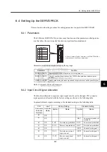
6.3.2 Electronic Gear Function
The electronic gear function enables the servomotor travel distance per input reference pulse
to be set to any value. It allows the host controller generating pulses to be used for control
without having to consider the machine deceleration ratio or the number of encoder pulses.
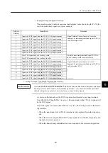
Setting the Electronic Gear
Calculate the electronic gear ratio (B/A) using the following procedure, and set the values in
parameters Pn202 and 203.
1. Check machine specifications.
Items related to the electronic gear:
• Deceleration ratio
• Ball screw pitch
• Pulley diameter
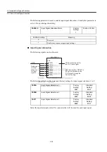
When the Electronic Gear
Function is Not Used
When the Electronic Gear
Function is Used
Ball screw pitch: 6m m (0.24 in)
Workpiece
No. of encoder pulses:2048
Equipment conditions and reference
units must be defined for the electronic
gear function beforehand.
To move a workpiece10 mm (0.39 in):
Reference unit is 1
µ
m. Therefore,
Reference unit: 1
µ
m
To move a workpiece 10 mm (0.39 in):
1 revolution is 6 mm.Therefore,
10
÷
6 = 1.6666 revolutions
2048
×
4 pulses is 1 revolution. Therefore,
1.6666
×
2048
×
4 = 13653 pulses
13653 pulses are input as references.
The equation must be calculated at the
host controller .
No. of encoder pulses:2048
10 mm
1
µ
= 10000 pulses
Workpiece
Ball screw pitch: 6 mm (0.24 in)
Ball screw pitch
Deceleration ratio


