244
YASKAWA
SIEPYAIH6B01A HV600 AC Drive Bypass Technical Reference
Note:
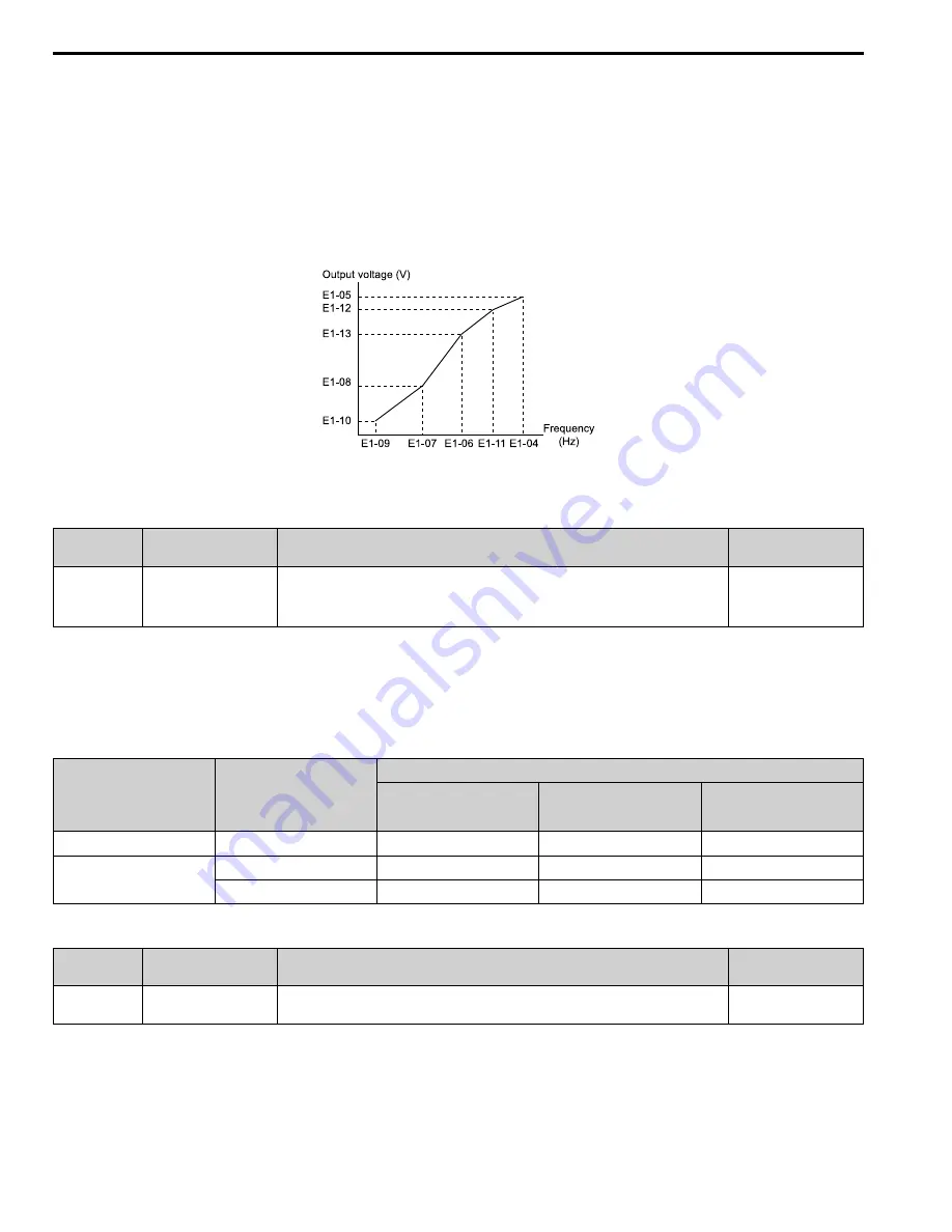
Be aware of the following points when manually setting V/f patterns.
•
To set linear V/f characteristics at frequencies lower than
E1-06 [Base Frequency]
, set
E1-07 = E1-09 [Mid Point A Frequency = Minimum
Output Frequency]
. In this application, the drive ignores
E1-08 [Mid Point A Voltage]
.
•
Set the five frequencies as specified by these rules: Incorrect settings will cause
oPE10 [V/f Data Setting Error]
.
E1-09 ≤ E1-07 < E1-06 ≤ E1-11 ≤ E1-04 [Minimum Output Frequency ≤ Mid Point A Frequency < Base Frequency ≤ Mid Point B
Frequency ≤ Maximum Output Frequency]
•
Setting
E1-11 = 0 [Mid Point B Frequency = 0 Hz]
disables
E1-12 [Mid Point B Voltage]
. Ensure that the four frequencies are set
according to the following rules;
E1-09 ≤ E1-07 < E1-06 ≤ E1-04
•
When you use
A1-03 [Initialize]
to initialize the drive, it will not reset
E1-03
.
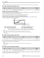
Figure 5.38 V/f Pattern
■
E1-01: Input AC Supply Voltage
No.
(Hex.)
Name
Description
Default
(Range)
E1-01
(0300)
Input AC Supply Voltage
Sets the drive input voltage.
208/240 V: 240 V,
480 V: 480 V
(208/240 V: 155 - 255 V,
480 V: 310 - 510 V)
NOTICE:
Set parameter E1-01 to align with the drive input voltage (not motor voltage). If this parameter is incorrect, the protective
functions of the drive will not operate correctly and it can cause damage to the drive.
Values Related to the Drive Input Voltage
The value set in
E1-01
is the base value that the drive uses for the motor protective functions in
. With a
480 V drive, the detection level changes for some motor protective functions.
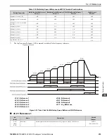
Table 5.34 Values Related to the Drive Input Voltage
Voltage
E1-01 Setting
Approximate Values
ov Detection Level
L2-05
[Undervoltage Detection Lvl
(Uv1)]
L3-17
[DC Bus Regulation Level]
208/240 V
All settings
410 V
190 V
375 V
480 V
Setting value ≥ 400 V
820 V
380 V
750 V
Setting value < 400 V
820 V
350 V
750 V
■
E1-03: V/f Pattern Selection
No.
(Hex.)
Name
Description
Default
(Range)
E1-03
(0302)
V/f Pattern Selection
Sets the V/f pattern for the drive and motor. You can use one of the preset patterns or you can make a
custom pattern.
F
(0 - F)
Note:
•
Set the correct V/f pattern for the application and operation area. An incorrect V/f pattern can decrease motor torque and increase current
from overexcitation.
•
Parameter
A1-03 [Initialize Parameters]
will not initialize the value of
E1-03
.
0 : Const Trq, 50Hz base, 50Hz max
Содержание H6B1A002
Страница 2: ...This Page Intentionally Blank 2 YASKAWA SIEPYAIH6B01A HV600 AC Drive Bypass Technical Reference...
Страница 12: ...12 YASKAWA SIEPYAIH6B01A HV600 AC Drive Bypass Technical Reference...
Страница 30: ...1 2 Catalog Code and Nameplate Check 30 YASKAWA SIEPYAIH6B01A HV600 AC Drive Bypass Technical Reference...
Страница 68: ...2 9 Knock Out Hole Dimensions 68 YASKAWA SIEPYAIH6B01A HV600 AC Drive Bypass Technical Reference...
Страница 74: ...Page Intentionally Blank...
Страница 76: ...Page Intentionally Blank...
Страница 454: ...5 14 Z Bypass Parameters 454 YASKAWA SIEPYAIH6B01A HV600 AC Drive Bypass Technical Reference...
Страница 590: ...8 6 Storage Guidelines 590 YASKAWA SIEPYAIH6B01A HV600 AC Drive Bypass Technical Reference...
Страница 694: ...9 19 Defaults by Bypass and Drive Model 694 YASKAWA SIEPYAIH6B01A HV600 AC Drive Bypass Technical Reference...
Страница 768: ...10 6 MEMOBUS Modbus Communications 768 YASKAWA SIEPYAIH6B01A HV600 AC Drive Bypass Technical Reference...
Страница 780: ...11 3 European Standards 780 YASKAWA SIEPYAIH6B01A HV600 AC Drive Bypass Technical Reference...


