60
YASKAWA
|
YASKAWA AC Drive
CR700
Catalog
|
KAEP C710617 24
Selection
■
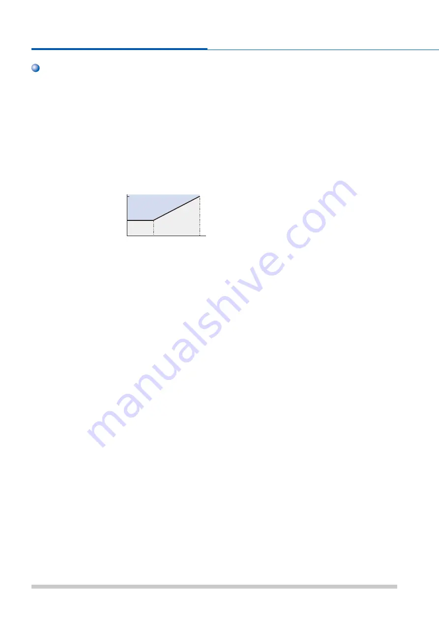
Installing a Reactor
An AC or DC reactor can be used for the following
situations:
・
when the power supply is
600 kVA or more.
・
to smooth peak current that results from switching a
phase advance capacitor.
・
to improve the power supply power factor.
The DC reactor is built in for models of catalog codes
CR
70
□
2088 and above, CR70
□
4045 and above.
Use an AC reactor when also connecting a thyristor
converter to the
same power
supply system,
regardless of the
conditions of the
power supply.
■
Emergency Stop
When the drive faults out, a protective circuit is activated
and drive output is shut off. This, however, does not stop
the motor immediately. Some type of mechanical brake
may be needed if it is necessary to halt the motor faster
than the Fast Stop function is able to.
■
Options
The B
1, B2,
−
,
+
1,
+
2 and
+
3 terminals are used to connect
optional devices. Connect only CR
700-compatible devices.
■
Repetitive Starting/Stopping
Using the drive with frequent starts and stops often
exceed
150% of the drive rated current values. Heat
stress generated from repetitive high current can shorten
the lifespan of the IGBTs. The expected lifespan for the
IGBTs is about
8 million start and stop cycles with a 2 kHz
carrier frequency and a
150% peak current.
Yaskawa recommends lowering the carrier frequency,
particularly when audible noise is not a concern. The user
can also choose to reduce the load, increase the
acceleration and deceleration times, or switch to a larger
drive. This will help keep peak current levels under
150%.
Be sure to check the peak current levels when starting
and stopping repeatedly during the initial test run, and
make adjustments accordingly.
For using the inching function in which the drives starts
and stops the motor repeatedly, Yaskawa recommends
the following steps to ensure torque levels:
・
Select a large enough drive so that peak current levels
remain below
150%.
・
The drive should be one frame size larger than the motor.
■
As the carrier frequency of the drive is increased above
the factory default setting, the drive
ʼ
s rated output current
must be derated. Refer to the instruction manual of the
drive for details on this function.
Installation
■
Enclosure Panels
Keep the drive in a clean environment by either selecting
an area free of airborne dust, lint, oil mist, corrosive gas,
and fl ammable gas, or install the drive in an enclosure
panel. Leave the required space between the drives to
provide for cooling, and take steps to ensure that the
ambient temperature remains within allowable limits. Keep
fl ammable materials away from the drive. If the drive must
be used in an area where it is subjected to oil mist and
excessive vibration, protective designs are available.
Contact Yaskawa for details.
■
Installation Direction
The drive should be installed upright as specifi ed in the
manual.
Settings
■
Use V/f Control when running multiple induction motors
at the same time.
■
Upper Limits
Because the drive is capable of running the motor at up to
590 Hz, be sure to set the upper limit for the frequency to
control the maximum speed. The default setting for the
maximum output frequency is
60 Hz.
■
Pay attention to the following points when using the
Virtual I/O function.
This function virtually wires the I/O terminal of the drive
internally.
Consequently, the behavior of the drive may differ from its
defaults, even if there is no wiring in the I/O terminal.
Before conducting a test operation, always check the
setting values for the parameter of the Virtual I/O function.
Failure to check may result in death or serious injury.
■
DC Injection Braking
Motor overheat can result if there is too much current
used during DC Injection Braking, or if the time for DC
Injection Braking is too long.
Application Notes
4000
600
0
60
400
Drive Capacity (kVA)
Power Supply Capacity
( kV
A)
Reactor required
Reactor
unnecessary
Application Notes


