background image

DC Inverter U-match Series Floor Ceiling Type Unit

37

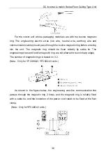
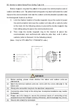
Buckle magnetic ring shall be added in the power line communication cord of 

outdoor and indoor unit. The added buckle magnetic ring shall be fixed at the outlet 
of power line communication cord near the outdoor unit side; detailed operation step 
for the magnetic buckle is as follow:

1)

Limit the fixation location of buckle magnetic ring at the outlet of power 
line communication cord near the outdoor unit side with a cable tie (refer 
to the mark 4 in the following picture) to prevent the buckle magnetic ring 
from sliding along the power line communication cord;

2)

Then clasp the buckle magnetic ring to the location of power line 
communication cord confirmed with cable tie, after that, re-fix it with a 
cable tie (refer to the mark 3 in the following picture) 

(Note

Only for

 YFC48G4T/O

YFC60G4T/O

units.)

WARNING!

(1) Before working, please check whether the indoor and outdoor units are 

powered on.   

(2) Match the terminal numbers and wire colors with the colors indicated in the 

indoor unit. 

(3) Wrong wire connection may burn the electrical components. 
(4) Connect the wires firmly to the wiring box. Incomplete installation may lead to 

fire hazard. 

(5) Please use wire clamps to secure the external covers of connecting wires. 

(Insulators must be clamped securely; otherwise, electric leakage may occur).

(6) Ground wire should be connected. 

Содержание U-match Series

Страница 1: ...ers DC Inverter U match Series Floor Ceiling Type Unit Models Indoor Unit Outdoor Unit YFC12G4 I YFC12G4 O YFC18G4 I YFC18G4 O YFC24G4 I YFC24G4 O YFC30G4 I YFC30G4 O YFC36G4 I YFC36G4 O YFC42G4 I YFC...

Страница 2: ...for maintaining normal communication of system and preheating refrigerant and lubricant If the product is not to be used for long cut off the power supply please energize and preheat the unit in advan...

Страница 3: ...turer 3 After verification the defect of product is directly caused by corrosive gas 4 After verification defects are due to improper operation during transportation of product 5 Operate repair mainta...

Страница 4: ...by Faults of the AC 47 5 2 Error Code 49 5 3 Unit Maintenance 52 5 4 Notice on Maintenance 55 5 5 After Sales Services 62 This marking indicates that this product should not be disposed with other ho...

Страница 5: ...se severe damage or death to people WARNING If not abide them strictly it may cause severe damage to the unit or the people NOTE If not abide them strictly it may cause slight or medium damage to the...

Страница 6: ...arts and plastic packing material must be treated in a safe way WARNING 1 Please install according to this instruction manual Installation must be performed in accordance with the requirement of NEC a...

Страница 7: ...Do not wash or sprinkle water on the air conditioner otherwise malfunction or electric shock will occur 15 Do not dry the filter with naked flame or an air blower otherwise the filter will be out of s...

Страница 8: ...s may deteriorate and fall off or even cause water leakage 2 Places with corrosive gas copper pipe or the welding parts may be corroded and cause refrigerant leakage 7 Adopt proper measures to protect...

Страница 9: ...indoor unit confirm the model of indoor unit and check the corresponding table B For outdoor unit that is installed or placed indoors select the corresponding table according to the height of the roo...

Страница 10: ...23 0 6 0 34 3 6 0 309 6 2 24 5 6 2 36 6 6 2 330 6 4 26 1 6 4 39 1 6 4 351 6 6 27 8 6 6 41 5 6 6 374 6 8 29 5 6 8 44 1 6 8 397 7 0 31 3 7 0 46 7 7 0 420 7 2 33 1 7 2 49 4 7 2 445 7 4 34 9 7 4 52 2 7 4...

Страница 11: ...lace with leakage of inflammable gas Selection of Installation Location for Indoor Unit Select a location pursuant to the following condition 1 Air inlet and outlet of the indoor unit should be away f...

Страница 12: ...bration of outdoor unit and allow the installation to be carried out safely 5 Avoid installing at a place with leakage of inflammable gas oil smoke or corrosive gas 6 Keep it away from strong wind bec...

Страница 13: ...65 YFC18G4 I 870 235 812 280 665 YFC24G4 I 1200 235 1142 280 665 YFC30G4 I 1200 235 1142 280 665 YFC36G4 I 1200 235 1142 280 665 YFC42G4 I 1570 235 1512 280 665 YFC48G4 I 1570 235 1512 280 665 YFC60G4...

Страница 14: ...Unit mm Dimensions Model A B C D E F G YFC12G4 O 732 330 553 455 310 675 285 YFC18G4 O 802 350 555 512 331 745 300 YFC24G4 O 958 402 660 570 371 889 340 YFC30G4 O 958 402 660 570 371 889 340 YFC36G4...

Страница 15: ...ake sure its installation space conforms to the following installation dimensions 1 When one outdoor unit is to be installed A E Hb Hd H mm a b c d e B 100 A B C 300 100 100 B E 100 1000 A B C E 300 1...

Страница 16: ...y side Unit mm A E Hb Hd H mm a b c d e A B C 300 300 1000 A B C E 300 300 1000 1000 D 2000 D E 2000 1000 B D Hb Hd Hd H 300 2000 Hb Hd Hd 1 2H 250 2000 1 2H Hd H 300 2500 B D E Hb Hd Hb 1 2H 300 2000...

Страница 17: ...DC Inverter U match Series Floor Ceiling Type Unit 13 3 When outdoor units are installed in rows Unit mm Hb H mm Hb 1 2H b 250 1 2H Hb H b 300 Hb H Prohibited...

Страница 18: ...ice for the best performance of indoor unit make sure its installation space conforms to the following installation dimensions 1 Install the unit at a place where is strong enough to withstand the wei...

Страница 19: ...hould be kept as much as possible so as for more convenient service 2 2 Unit Installation 2 2 1 Indoor Unit Installation 2 2 1 1 Preparation for Installing the Indoor Unit 1 Dismantle the clasp in the...

Страница 20: ...the paper template 2 Insert the anchor bolts into the drilled holes and drive the pins completely into the anchor bolts with a hammer 3 Remove the right and left side panels 4 Put the hanger bolt int...

Страница 21: ...make the drain pipe slant slightly downward so that the drainage will become much smoother 7 Reinstall and tighten the right and left side panel 8 When installing the floor ceiling type unit if user...

Страница 22: ...p of the building 3 If it vibrates and causes noise please add rubber cushion between the outdoor unit and the installation base 4 When the outdoor unit is in heating or defrosting it needs to drain w...

Страница 23: ...and weld again NOTES 1 The air conditioner must be installed in a room that is larger than the minimum room area And it is not allowed to use in a room that has running fire 2 Before break the connec...

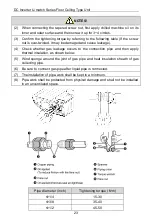
Страница 24: ...30 Connection pipe should adopt water proof insulating material Its wall thickness should be 0 5 1 0mm and the pipe wall should be able to withstand 6 0MPa The longer the connection pipe is the worse...

Страница 25: ...the making of oil return bend are as follows A inch B mm C mm 3 8 20 150 1 2 26 150 5 8 33 150 2 2 3 2 Pipe Flaring 1 Cut the connection pipe with a pipe cutter 2 The mouth of connection pipe should...

Страница 26: ...become hard and difficult to be bent or extended So do not bend or extend the pipe for more than 3 times 4 When bending the pipe do not bend it excessively otherwise it will get broken As shown beside...

Страница 27: ...ed and cause leakage 4 Check whether gas leakage occurs to the connection pipe and then apply thermal insulation as shown below 5 Wind sponge around the joint of gas pipe and heat insulation sheath of...

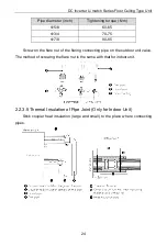
Страница 28: ...75 7 8 80 85 Screw on the flare nut of the flaring connecting pipe on the outdoor unit valve The method of screwing the flare nut is the same with that for indoor unit 2 2 3 5 Thermal Insulation of Pi...

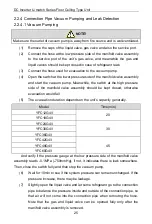
Страница 29: ...of the manifold valve assembly should be kept closed otherwise evacuation would fail 5 The evacuation duration depends on the unit s capacity generally Model Time min YFC12G4 I 20 YFC18G4 I YFC24G4 I...

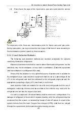
Страница 30: ...nsure that the detector is not a potential source of ignition and is suitable for the refrigerant used Leak detection equipment shall be set at a percentage of the LFL of the refrigerant and shall be...

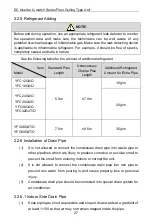
Страница 31: ...t for Extra Pipe YFC12G4 O 5 0m 7 0m 16 g m YFC18G4 O YFC24G4 O 20 g m YFC30G4 O YFC36G4 O YFC42G4T O 7 5m 9 5m 35 g m YFC48G4T O YFC60G4T O 2 2 6 Installation of Drain Pipe 1 It is not allowed to con...

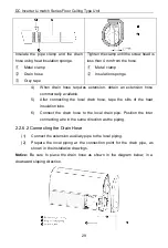
Страница 32: ...y rigged piping could lead to leaks and eventually wet furniture and belongings 4 Connect the drain hose 5 Installing the Drain Pipes 1 For determining the position of the drain hose perform the follo...

Страница 33: ...mercially available 5 After connecting the local drain hose tape the slits of the heat insulation tube 6 Connect the drain hose to the local drain pipe Position the inter connecting wire in the same d...

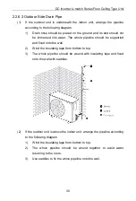
Страница 34: ...whole pipeline should be supported and fixed onto the wall 2 Wind the insulating tape from bottom to top 3 The whole pipeline should be wound with insulating tape and fixed onto the wall with saddles...

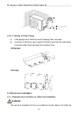
Страница 35: ...ws smoothly 2 As shown in the figure pour water into the drain pan from the right side to check that water flows smoothly from the drain hose Ceiling type Floor type 2 3 Electrical Installation 2 3 1...

Страница 36: ...ds can t directly contact any hot objects For example they must not contact chimney pipes warm gas pipes or other hot objects The external power cord communication cords and the connection wire of ind...

Страница 37: ...ed wires Wiring work must be done according to national wiring rules and regulations 2 3 2 Electrical Parameters 2 3 2 1 Wire Specifications and Fuse Capacity Model Power Supply Fuse Capacity Min sect...

Страница 38: ...a proper length according to local conditions To be in compliance EN 55014 it is necessary to use 8 meters long wire Adopt 2pc of 0 75mm power cords to be the communication cords between wired contro...

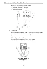
Страница 39: ...en peel away about 10mm of the insulation layer 2 Use a screwdriver to unscrew the terminal screw on the terminal board 3 Use a round terminal fastener or clamp to fix the round terminal firmly on the...

Страница 40: ...The magnetic ring should be fixed reliably by cable tie The engineering wires and buckle magnetic ring are not allowed to touch sharp edges The number of magnetic rings is based on 3 2 Note Only for...

Страница 41: ...e power line communication cord 2 Then clasp the buckle magnetic ring to the location of power line communication cord confirmed with cable tie after that re fix it with a cable tie refer to the mark...

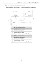
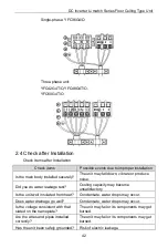
Страница 42: ...or units Single phase unit YFC12G4 O YFC18G4 O YFC24G4 O YFC30G4 O YFC12G4 I YFC12G4 O YFC18G4 I YFC18G4 O Power cords 3 1 5mm Power cords 4 1 0mm Communication cords 2 0 75mm YFC24G4 I YFC24G4 O YFC3...

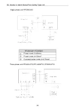
Страница 43: ...U match Series Floor Ceiling Type Unit 39 Single phase unit YFC36G4 O Power cords 3 4 0mm2 Power cords 4 1 0mm2 Communication cords 2 0 75mm2 Three phase unit YFC42G4T O YFC48G4T O YFC60G4T O YFC36G4...

Страница 44: ...Use screws to tighten up the connection wires and power cords of indoor and outdoor units on the terminal board Wrong connection may lead to fire hazard 5 If the connection wires of indoor unit outdo...

Страница 45: ...C24G4 I YFC30G4 I YFC36G4 I YFC42G4 I YFC48G4 I YFC60G4 I 2 Outdoor side Remove the big handle front panel of the outdoor unit and insert one end of the communication cord and the power cord to the te...

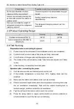
Страница 46: ...down vibrate or produce noise Did you do water leakage test Cooling capacity may become unsatisfactory Is the unit well insulated from heat Condensate water drops may occur Does water drainage go well...

Страница 47: ...nstallation work is not completed 2 Control circuit is correct and all the wires are firmly connected 3 Cut off valves of the gas pipe and liquid pipe are open 4 The inside of the unit should be clean...

Страница 48: ...ately turn the unit on again compressor will need 3min to restart Even if you press ON OFF button on the remote controller it won t be started up right away If there s no display on the wired controll...

Страница 49: ...DC Inverter U match Series Floor Ceiling Type Unit 45 3 Product Introduction 3 1 Overall Layout NOTE The connection pipe drain pipe power cord for this unit should be prepared by the user...

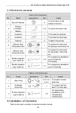
Страница 50: ...pe connecting nut 7 Ordinary Nut Tamperproof box 1 To prevent the removal of the liquid pipe connecting nut 8 Buckle magnetic ring Cable tie 1 2 For engineering installation only YFC48G4 I YFC60G4 I 9...

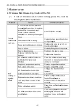
Страница 51: ...is resumed Power plug is loose Re insert the power plug Remote controller has low battery Replace the batteries Bad cooling or heating effect Air inlet and outlet of indoor or outdoor units have been...

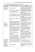
Страница 52: ...here is refrigerant brushing sound when defrosting under heating It s the sound of 4 way valve switching direction The sound will disappear after the valve changes its direction There is hissing sound...

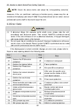
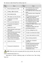
Страница 53: ...rvice staff to repair If the display panel or wired controller displays an error code please refer to the error code meaning stated in the following table Error code Error Error code Error A1 Outdoor...

Страница 54: ...or anti phase protection q2 DC indoor fan AC current protection E0 Indoor fan error q3 DC indoor fan driver IPM module protection E1 Compressor high pressure protection q4 DC indoor fan driver PFC pr...

Страница 55: ...circuit detection error L3 Outdoor fan 1 error U2 Compressor phase loss and anti phase protection L4 Wired controller power supply circuit poor U3 DC bus voltage drop error L5 Wired controller power...

Страница 56: ...tivated while it will go out when HEAT is deactivated Indicating Lamp of TIMER The indicating lamp will shine when TIMER is activated while it will go out when TIMER is deactivated or the set 5 3 Unit...

Страница 57: ...ner or wash it by flashing water If the oil stain on the filter cannot be removed or cleaned up wash it by warm water meld with the detergent Dry the filer in the shadow NOTES A Never use hot water ov...

Страница 58: ...been used for a long period NOTE all above should be operated by the skilled serviceman 3 At the End of the Seasonal Use 1 Cut off the power supply main switch 2 Clean the air filters and other parts...

Страница 59: ...the dust and sundries in indoor and outdoor unit 4 If the outdoor unit is rusty coat the rusty location with paint to prevent it from expanding 5 3 6 Components Replacement Components are available i...

Страница 60: ...hand Have a dry powder or CO2 fire extinguisher adjacent to the charging area 5 4 1 6 No Ignition Sources No person carrying out work in relation to a refrigeration system which involves exposing any...

Страница 61: ...ion pipe or components are installed in a position where they are unlikely to be exposed to any substance which may corrode refrigerant containing components unless the components are constructed of m...

Страница 62: ...ds etc Ensure that apparatus is mounted securely Ensure that seals or sealing materials have not degraded such that they no longer serve the purpose of preventing the ingress of flammable atmospheres...

Страница 63: ...following procedure shall be adhered to 1 Remove refrigerant 2 Purge the circuit with inert gas 3 Evacuate 4 Purge again with inert gas 5 Open the circuit by cutting or brazing The refrigerant charge...

Страница 64: ...issioning A follow up leak test shall be carried out prior to leaving the site 5 4 8 Decommissioning Before carrying out this procedure it is essential that the technician is completely familiar with...

Страница 65: ...ess it has been cleaned and checked 5 4 9 Labelling Equipment shall be labelled stating that it has been de commissioned and emptied of refrigerant The label shall be dated and signed Ensure that ther...

Страница 66: ...ufacturer if in doubt The recovered refrigerant shall be returned to the refrigerant supplier in the correct recovery cylinder and the relevant Waste Transfer Notice arranged Do not mix refrigerants i...

Страница 67: ......

Страница 68: ......

Отзывы: