


– 17 –
5. Remove spring plate (C-17).
6. Loosen holder (C-12).
7. Remove main needle (C-16) assembly.
8. Remove plugs (C-36, 28) and pilot screw (C-38).
9. Remove jet (C-27, 30, 31).
10. Clean body and all parts in clean solvent.
11. If extremely corroded or dirty, soaking in commercial carburettor cleaner is recom-
mended.
B. Inspection
1. Inspect float needle for straightness.
2. lnspect float needle contact.
3. Inspect all passage ways and jets for obstructions.
C. Reassemble in Reverse Order
CAUTION:
1. Check throttle butterfly for smooth movement and proper return.
2. Set float level to 29 mm. Measure from tip of float pin to top of float.
See figure 15.
Figure 15
3. Do not misplace main air jet, (C-30) and slow air jet (C-31). Main air jet has an I.D. of
1.5 mm (0.059”). Slow air jet (C-31) has an I.D. of 0.9 mm (0.036”) and is located
behind above jet.
4. Adjust link bar (P-87) only at closed throttle. Be sure throttle butterfly closes fully and
smoothly.
5. Turn pilot screw clockwise to its full and reverse 1
1
/
4
turn for standard.
Содержание 302
Страница 1: ...302 YAMATO MOTOR CO LTD Ota Japan November 2012 M O D E L M A N U A L ...
Страница 2: ...YAMATO EUROpE www YamatoRacing co uk ...
Страница 14: ... 11 pOWER UNIT GROUp ...
Страница 15: ...pOWER UNIT GROUp 12 ...
Страница 18: ... 15 MAGNETO GROUp ...
Страница 19: ... 16 CARBURETTOR GROUp ...
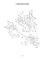
Страница 23: ... 20 LOWER UNIT GROUp ...
Страница 24: ... 21 LOWER UNIT GROUp ...
Страница 25: ...GEAR CASE GROUp 22 ...
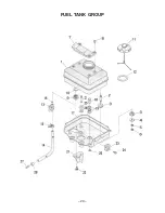
Страница 26: ... 23 FUEL TANK GROUp ...
Страница 27: ... 24 IV TROUBLESHOOTING ...
Страница 28: ... 25 V CROSS SECTION OF MOTOR ...